
outer reference shaft, The displacement between
indicator (fig. 6-62). The system measures the
the shafts is proportional to the torque load on
torsional deflection (twist) of the extension shaft
the driving shaft. This displacement causes a phase
as it sends power from the engine to the propeller.
displacement between the pickup signals. The
Magnetic pickups detect and measure this deflec-
phase angle of the resultant signal is linearly
tion electronically. The indicator registers the
proportional to the shaft deflection. The phase
amount of deflection in shaft horsepower.
detector and amplifier in the indicator converts
The extension shaft of the engine consists of
the signal to current. The current goes to a
two concentric shafts. The inner shaft is the power
servomotor, which drives the indicator pointers.
transmitting shaft. The outer shaft attaches to the
The servomotor also drives the rotor of a synchro
inner shaft at the rear end. Toothed flanges on
control transformer in the indicator. The synchro
the front end of each shaft rotate in the field of
control transformer balances the synchro
magnetic pickups. When the engine is running,
system when the pointer registers the measured
the teeth on the flange of the driving (inner) shaft
move in relation to the teeth on the flange of the
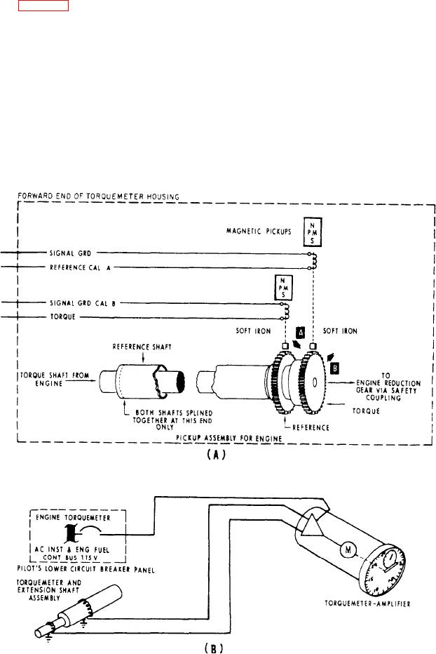
Figure 6-62.-Torquemeter system: (A) pickup assembly; (B) indicating system.
6-56