
when using the reset knob to set the reading on
the pounds-fuel-remaining indicator.
OIL PRESSURE SYSTEM
Oil pressure instruments show that oil is or is
not circulating under proper pressure. An oil
pressure drop warns of impending engine failure
due to lack of oil, oil pump failure, or broken
lines. Oil pressure shows on an engine gauge unit
(fig. 6-56). This unit consists of three separate
gauges in a single case--oil pressure, fuel pressure,
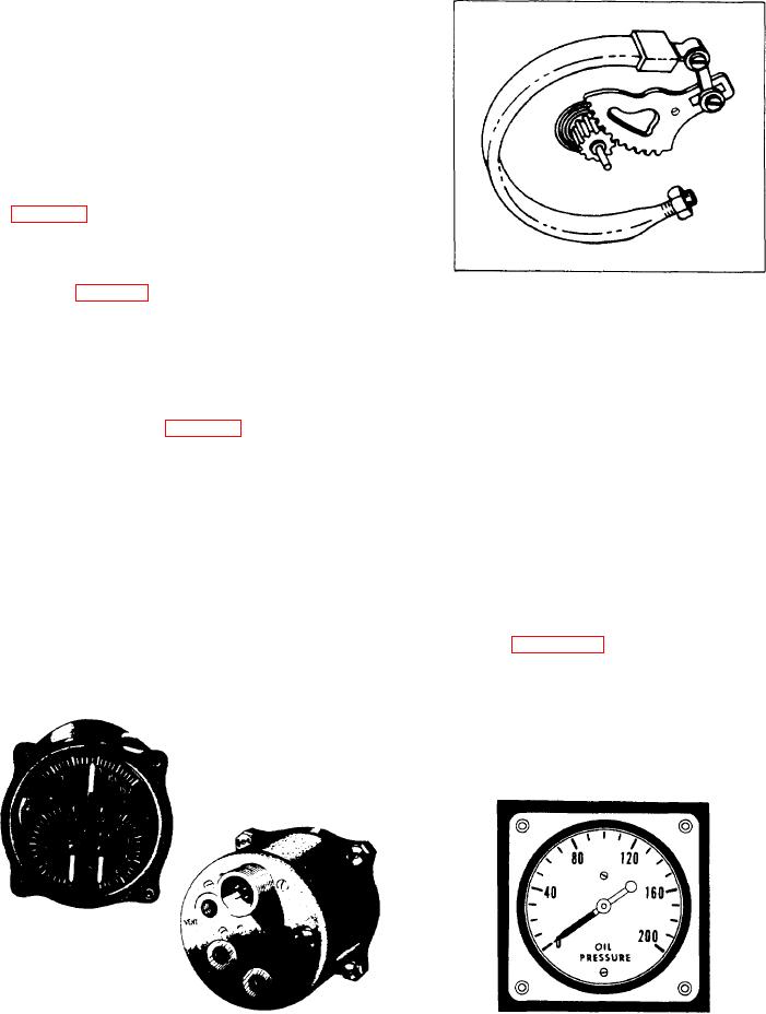
and oil temperature. The gauge has a Bourdon
tube mechanism for measuring fluid under
pressure (fig. 6-57). The instrument's oil pressure
range is from 0 to 200 PSI. You read the scale
Figure 6-57.-Bourdon tube oil pressure gauge.
in graduations of 10 PSI. There is a single
connection on the back of the case leading directly
into the Bourdon tube.
of fire, loss of oil or fuel, and mechanical
difficulties.
In some aircraft, the oil pressure gauge is a
separate instrument (fig. 6-58). This instrument
The synchro system consists of a synchro
operates on the Bourdon tube principle.
indicator and transmitter. The synchro transmitter
consists of a permanent magnet moving within a
The synchro system is another method of
stator. The stator is a circular core of magnetic
material wrapped with a single, continuous
measuring oil under pressure. This type of oil
pressure system is used on most modern aircraft.
toroidal winding. Taps divide the winding into
Essentially, it is a method of directly measuring
three sections. Voltages in each of the sections
engine oil pressure. After taking the measure-
vary with the position of the permanent magnet.
ments, they go electrically from the point of
As the magnet moves, the ratio between the three
measurement to the synchro indicator on the
signal voltages varies accordingly.
instrument panel. The synchro system ends the
need for direct pressure lines from the engine to
Look at figure 6-59. Here, you can see the
the instrument panel. It also reduces the chances
transmitter and indicator connect in parallel.
When excited by the same fundamental source,
the signal voltages in corresponding sections of
the two stators are equal and balanced. The signal
voltages remain equal and balanced as long as the
Figure 6-56.-Engine gauge unit.
Figure 6-58.-Bourdon tube oil pressure instrument.