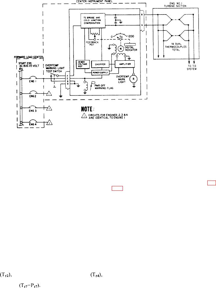
Figure 6-51.-Turbine inlet temperature indicator system.
the junctions become hot, a reaction between the
temperature (TIT) reaches 1,082C. At this point,
dissimilar metal generates a dc voltage. A
a switch in the indicator closes to energize the
thermocouple harness connects the thermocouples
warning light. One test switch installed external
in parallel to provide an average heat signal from
to the indicators lets the crew test all the indicator
each station.
overtemperature warning lights at once. The test
The thermocouple temperature indicator (fig.
switch simulates an overtemperature signal in each
6-46) displays turbine inlet gas temperature on two
indicator's temperature control bridge circuit.
vertical scales, one for each engine. The scales are
When power to an indicator fails, a red
linear from 0 to 6; segmented in tens, from 6 to
warning flag becomes visible. Also, the indicator
14 and multiplied by 100C when read. OFF
pointers maintain their position, and the over-
failure flags appear at the upper left and right of
temperature warning light becomes inoperative.
the indicator to show loss of signal input or
The indicator scale is calibrated in degrees
electrical power.
Centigrade from 0 to 12 (times 100C). The digital
indicator goes from 0C to 1,200C in 2-degree
Internally, the indicator has two channels, one
for each engine. The channels basically consist
increments.
of a cold junction compensator, rebalance
The F-14 aircraft also used the thermocouple
potentiometer, chopper, servo amplifier, servo-
principle for indicating engine turbine inlet
motor, and gear train. Thermocouple signal
temperatures. Each engine has 10 thermocouple
voltage from the engines goes to the cold junction
probes, distributed at three stations on the engine.
They measure and average engine turbine inlet
compensator in each channel. The compensator
provides corrective voltages to counteract the
temperature. There are three types of thermo-
effect of secondary thermocouple junctions
couple probes--compressor inlet temperature
in the indicator when Alumel and Chromel
compressor discharge temperature
leads connect to copper ones. A stable voltage
and exhaust gas temperature thermocouple
Each thermocouple probe has
pressure
goes to the old junction compensator and
rebalance potentiometer.
one or more Alumel-Chromel junctions. When
6-47

