
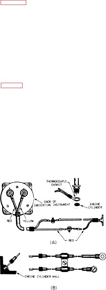
figure 6-50. In the gasket thermocouple, the rings
the thermocouple harness terminal block to the
indicator. Plugs in the thermocouple circuits are
of two dissimilar metals are pressed together,
forming a spark plug gasket. Each lead that
also of a special type. The thermocouple harness
mounts on the turbine unit aft of the thermo-
connects back to the galvanometers must be of the
couple. The harness includes separate leads for
same metal as the thermocouple part to which it
connects. For example, a copper wire connects to
each of the 18 thermocouples, and it maintains
the copper ring, and a constantan wire connects
two electrically separate circuits. The harness is
located inside a rigid metal, channel type of
to the constantan ring. Thermocouple leads are
housing and cover. The leads and terminals
critical in makeup and length because the
project through holes in the front side of the
galvanometers are calibrated for a specific set of
leads in the circuits.
housing wall. Electrical signals from the 18
dual-junction thermocouples are averaged within
the harness.
TURBINE INLET TEMPERATURE (TIT)
The thermocouple assemblies mount on pads
INDICATOR SYSTEM. --Some aircraft have an
provided around the turbine inlet case. Each
engine turbine inlet temperature indicator system
(fig. 6-51) to provide a visual indication of
thermocouple incorporates two electrically
independent junctions within a sampling type
temperatures entering the turbine. The tempera-
probe. AL identifies Alumel terminal studs, and
ture of each engine turbine inlet is measured by
CR identifies Chromel terminal studs.
18 dual-unit thermocouples in the turbine inlet
Since the average voltage of the thermocouples
casing. These dual thermocouples are connected
in parallel. One set sends signals through a harness
at the thermocouple terminal blocks represents the
and aircraft wiring to an indicator. The other
turbine inlet temperature, it is necessary that no
interference with the signal take place while the
set of thermocouples provides signals to the
signal goes to the indicator. Therefore, the wiring
temperature datum control. Each circuit is
from the thermocouple terminal block to the
electrically independent and provides dual system
dependability.
indicator goes through the harness. The harness
wiring goes separately from other interference-
All parts of the engine temperature measure-
producing wiring.
ment system are made of Chromel and Alumel
The indicator contains a bridge circuit with
material, including welds. Special wiring and
wire identification are in the aircraft from
cold junction compensation, a two-phase motor
to drive the pointer, and a feedback potenti-
ometer. Also included in the indicator is the Zener
voltage reference circuit, a chopper circuit, an
amplifier, power supply, a power-off flag, and
an overtemp warning light.
Output of the bridge circuit goes to the
chopper circuit, so the bridge circuit isn't loaded.
The chopper output goes to the amplifier. Output
of the amplifier feeds the variable field of
a two-phase motor. This field positions the
indicator main pointer and the digital indicator,
The motor also drives the feedback potentiometer
to provide a nulling signal. The signal is relative
to the temperature signal and stops the drive
motor upon reaching the correct pointer position.
The Zener diode circuit protides a closely
regulated reference voltage in the bridge, This
signal avoids the error caused by voltage variation
from the indicator power supply. The indicator
power supply powers the Zener circuit, the
chopper, and the amplifier. It also powers the
power off warning flag and the fixed field of the
two-phase motor.
The overtemperature warning light in the
indicator comes on when the turbine inlet
Figure 6-50.-Thermocouples: (A) gasket type; (B) rivet type.
6-46