
generator in which it is used. The two end shields
motion of the permanent magnet rotor. The
are of die-cast aluminum alloy. They serve to
spring is secured to the shaft to transmit torque
support the generator stator and rotor by means
from the rotor to the shaft. Ball bearings in the
of a receptacle (callout 9). The receptacle attaches
motor end shields support the shaft. These end
to the junction box (callout 10) of the generator.
shields also serve to locate the stator. This lets all
parts of the motor maintain their proper position
Tachometer Indicators
with respect to each other.
The armature of the synchronous motor
Tachometer indicators mount on the cockpit
consists mainly of the permanent magnet and the
instrument panel. They are relatively small in size.
hysteresis disk. The purpose of the permanent-
The type of unit varies. Depending on the
magnet material is to provide starting and running
particular installation, some are single element
torque at low speeds. The hysteresis disk provides
and others are dual element, The operating
starting torque at high speed. This is necessary
principles of the two types are basically the same.
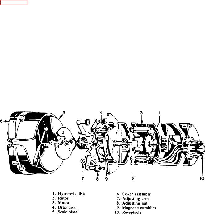
Figure 6-45 shows a cutaway view of a single-
permanent magnet, by itself, cannot pull into step.
element tachometer (radial) indicator. The unit
At the higher speeds, the hysteresis disk moves
consists essentially of two parts a synchronous
the rotor up to near synchronism, and then the
motor and an indicating element. The motor runs
permanent magnet pulls it into exact synchronism.
in synchronism with the tachometer generator. It
One end of the motor shaft extends through
also drives the indicating element through a
the front end shield and supports the drag-magnet
magnetic-drag coupling. The indicating element
assembly (callout 9). The drag-magnet assembly,
indicates the speed of the synchronous motor,
which is driven by the synchronous motor,
and, therefore, the speed of the aircraft engine.
consists of two plates to which small permanent
The synchronous motor (callout 3) consists of
magnets attach. The arrangement of the magnets
a three-phase stator winding that goes in, and is
concentrate the flux near the outside edge of the
insulated from, a laminated circular core. Within
drag disk. This arrangement obtains maximum
the circular core is a shaft. The rotating parts
torque with minimum weight. Between the two,
attach to this shaft. A cotter pin secures a
plates carrying the magnets is a disk (callout 4)
hysteresis disk (callout 1) to the shaft. A
of conducting material. This material is an alloy
permanent magnet rotor (callout 2) is free to move
having a low-temperature coefficient. This
on the shaft. The hysteresis disk at one shaft end
prevents temperature changes from affecting the
and a spring at the other restrain longitudinal
material's resistance. The magnet assembly
Figure 6-45.-Cutaway view of a tachometer indicator (radial).