
originating in the aircraft drive shaft. It will also
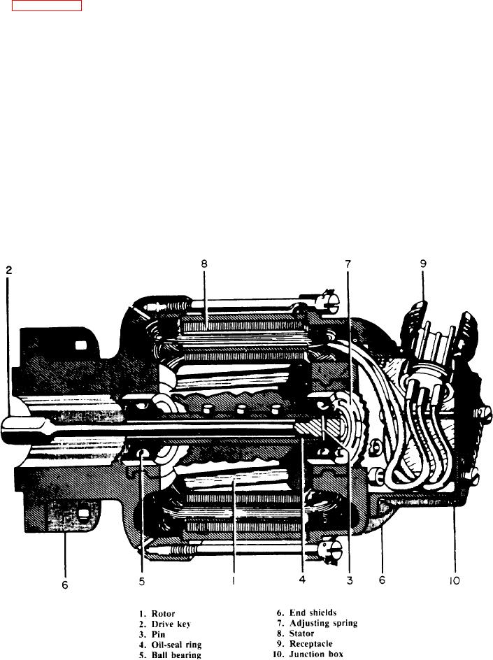
Figure 6-44 shows a cutaway view of a
accommodate small misalignments between the
tachometer generator. You should refer to it while
generator and its mounting surfaces. This key goes
you read this section. The generator consists
into the hollow rotor shaft. A pin (callout 3) at
essentially of a permanent-magnet rotor (callout
the end opposite the drive shaft secures the key
1) and a stator (callout 8) that develop three-phase
in place. An oil-seal ring (callout 4) is located
power as the rotor turns.
inside the hollow shaft and over this key. This seal
The armature of the generator consists of a
prevents oil from leaking into the generator
magnetized rotor. The rotor is cast directly onto
through the hollow shaft. The shaft runs in two
the generator shaft. The generator may be of
ball bearings (callout 5) set in stainless steel inserts.
either two- or four-pole construction. The two-
The inserts are cast directly into the generator end
and four-pole rotors are identical in appearance
shields (callout 6). An adjusting spring (callout
and construction. They differ in that the two-pole
7) at the receptacle end of the shaft maintains the
rotor is magnetized north and south diametrically
proper amount of end play.
across the rotor, while the four-pole rotor is
The stator consists of a steel ring with a
magnetized alternately north and south at each
laminated core of ferromagnetic material. A
of the four pole faces.
three-phase winding goes around this core and is
The key (callout 2) that drives the rotor is a
insulated from it. The winding is adapted for
long, slender shaft. It has enough flexibility to
two- or four-pole construction, depending on the
prevent failure under the torsional oscillations
Figure 6-44.-Cutaway view of a tachometer generator.
6-40