
MISCELLANEOUS FLIGHT
center, it shows the aircraft is flying straight. If
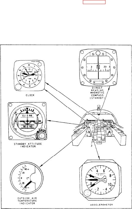
INSTRUMENTS
it moves off center, it shows the aircraft is turning
in the direction of the pointer deflection. The turn
The pilot uses several other indicators to
needle shows the rate (number of degrees per
control the aircraft. These indicators are not
minute) at which the aircraft is turning.
always useful, but they come into play under
By using the turn-and-bank indicator, the pilot
special flight conditions. As you read this section,
checks for coordination and balance in straight
look at figure 6-41.
flight and in turns. By cross-checking this
instrument against the airspeed indicator, the
Accelerometer Indicators
relation between the aircraft lateral axis and the
horizon can be determined. For any given
The pilot must limit aircraft maneuvers so
airspeed, there is a definite angle of bank
various combinations of acceleration, airspeed,
necessary to maintain a coordinated turn at a
gross weight, and altitude remain within specified
given rate.
Figure 6-41.-Miscellaneous flight instruments.
6-35