
completes a circuit to power its respective
caution indicator light on the pilot CAUTION
ADVISORY indicator.
TEMPERATURE INDICATING
SYSTEMS
To properly monitor the operation of an
aircraft engine, you must know various tempera-
ture indications. Some of the more important
indications include the temperatures of the engine
oil, free air, and exhaust systems of jet engines.
Various types of thermometers, such as the
bimetal and resistance types, collect and present
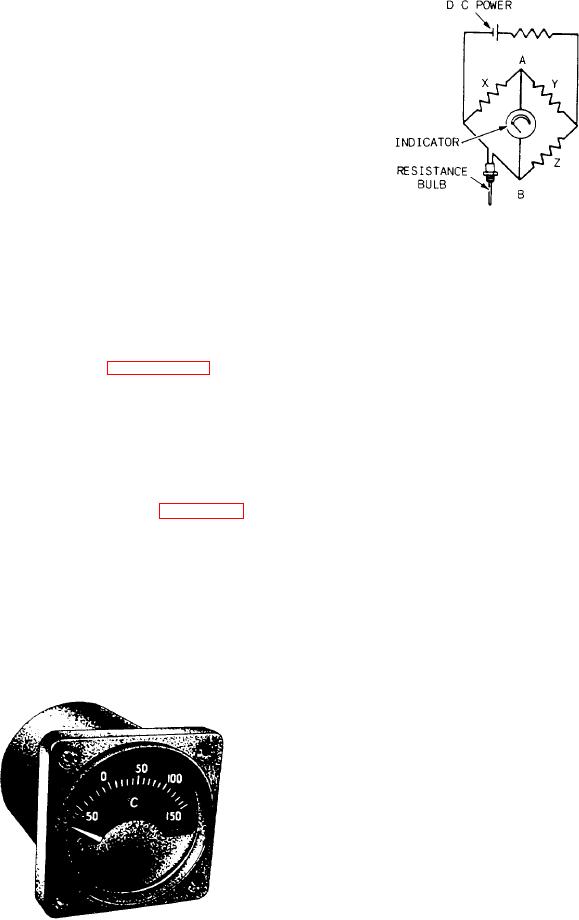
Figure 6-48.-Wheatstone bridge thermometer.
this information.
The main parts of resistance thermometers are
the indicating instrument, the temperature-
resistance of arms X, Y, and Z are also 100 ohms
sensitive element (resistance bulb), and the
each. At this temperature the Wheatstone bridge
connecting wires leading from the bulb.
is in balance. This means the sum resistance of
The indicator dials of resistance thermometers
X and Y equals the sum resistance of the bulb and
are calibrated according to the range of tempera-
Z. Therefore, the same amount of current flows
ture to be measured. Figure 6-47 shows a
in both sides of this parallel circuit. Since
resistance thermometer indicator. The indicators
all four sides are equal in resistance, the
are self-compensating, allowing for the changes
voltage drop across side X equals the drop across
in cockpit temperatures.
the bulb. Since these voltages are equal, the
voltage from A to B is zero, and the indicator
Wheatstone Bridge System
reads zero.
A schematic diagram of a Whetstone bridge
NOTE: If there is an open in the voltage
thermometer circuit is shown in figure 6-48. You
should refer to it as you read this section. The
supply circuit, the galvanometers will also read
zero.
resistance bulb element is one side of the
Wheatstone bridge circuit. The other three sides
When the temperature of the bulb increases,
are resistors in the indicating meter. The circuit
receives voltage from the aircraft dc power supply.
its resistance also increases. This unbalances the
When the temperature bulb senses a tempera-
bridge circuit causing the needle to deflect
ture of 0C, its resistance is 100 ohms. The
to the right. When the temperature of the bulb
decreases, its resistance decreases. Again the
bridge circuit goes out of balance. However, this
time the needle swings to the left.
The galvanometers is calibrated so the amount
of deflection causes the needle to point to
the number of the meter scale. This number
corresponds to the temperature at the location of
the resistance bulb.
This instrument requires a constant and steady
supply of dc voltage. Fluctuations in the power
supply affect total bridge current, which can cause
an unbalanced bridge. Unless excessive heat
damages the bulb, it will give accurate service
indefinitely. When a thermometer does not
operate properly, check carefully for loose wiring
connections before replacing the bulb.
Figure 6-47.-Indicator of a resistance thermometer.