see an indication of a loaded filter after the fluid
reaches normal operating temperature (85°F
minimum), shut down the test stand and have
replacement filter elements installed. On test stands
that have a fluid sight glass and manual air bleed
valve, periodically operate the valve and monitor the
sight glass throughout the cleaning cycle to eliminate
visible indications of entrapped air.
When recirculation cleaning and deaeration are
complete, analyze the hydraulic fluid for contamin-
nation Terminate the fluid flow to the external
service hoses in preparation for connecting them to
the aircraft. Disconnect the service hoses from
manifold assembly and reinstall the manifold dust
covers.
APPLYING HYDRAULIC POWER.— Before
you connect a test stand to an aircraft system, make
sure that all personnel, workstands, and other
ground-handling equipment are clear of flight control
surfaces, movable doors, and other units. Stay clear
of these areas when either electric power or hydraulic
pressure is applied to the aircraft. Sudden movement
can cause injury or damage.
NOTE: Refer to the applicable maintenance
manual for the specific procedures to follow
when applying external electric and hydraulic
power.
Before connecting the hydraulic test stand to the
aircraft, set the test stand controls to the positions and
values required to accomplish the aircraft tests.
Operate the test stand to confirm the settings. Reduce
the volume adjustment to minimum flow and shut
down the stand. Connect the test service hoses to the
aircraft ground power quick-disconnects, making sure
that all connectors are clean before connection. Mate
all the attached dust caps and plugs to protect against
their contamination during test stand operation.
Do not kink or damage test stand hoses when
connecting them to aircraft systems. Keep the hoses
uniformly bent while bending around structures or
equipment. Maintain and follow the recommended
minimum inside bend radii. A 1/2-inch pressure hose
should have a 2.30-inch radius, a 5/8-inch pressure
hose a 5.37-inch radius, and a 1-inch hose a 5.90-inch
radius.
Before you can apply hydraulic power, you need
to check the aircraft reservoir level. Fill it to the level
specified in the applicable MIM or MRC. If
necessary, service the reservoir using an approved
fluid service unit. Then, set up the test stand for either
aircraft or test stand reservoir operation, as specified
in the applicable MIM. You can set the required mode
of operation by using the reservoir selector valve on
stands that have this equipment, or use the reservoir
fluid supply valve.
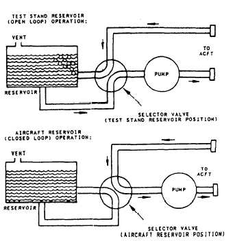
When the test stand reservoir
supply valve is closed, the aircraft reservoir will
operate. The test stand reservoir is preferred because
the vented reservoir allows aircraft fluid deaeration
during system operation (fig. 4-15). Use this mode
whenever practical.
When a test stand is equipped with return line,
back pressure reducing valves, test stand reservoir
operation can be used even in situations where the
aircraft reservoir is normally used. Adjust the back
pressure reducing valve by presetting the value
equivalent to normal aircraft reservoir pressure.
Make sure that the aircraft controls are in the
specified ground check positions required for
obtaining normal reservoir fluid level. Apply external
hydraulic power and trim the back pressure reducing
valve until a stable, proper fluid level is obtained in
the aircraft reservoir. Periodically check the fluid
level. Ensure back pressure reducing valve is set
properly or the aircraft may be damaged by
overpressurization.
After you have adjusted the back pressure
reducing valve, you can start the test stand, and allow
Figure 4-15.—Test stand operating modes.
4-34


