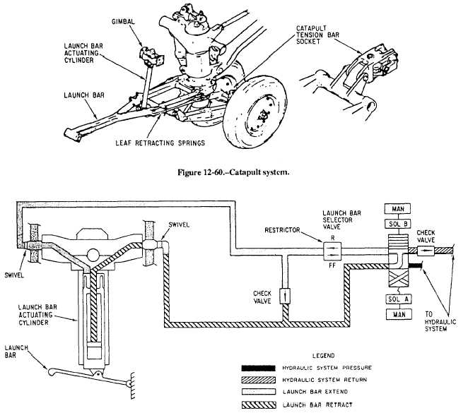
Figure 12-61.—Catapult system hydraulic schematic.
harnesses. The system consists of a catapult launch bar,
a launch bar actuating cylinder and gimbal, selector
valve, leaf retracting springs, and a catapult tension bar
socket. See figure 12-60.
The launch bar is swivel mounted on the forward
side of the nose gear outer cylinder and maybe extended
and retracted during taxiing. The launch bar is
automatically retracted after catapulting. A launch bar
warning light on the main instrument panel comes on
any time the following conditions exist:
• The launch bar control switch is in EXTEND.
• The selector valve is in bar extended position.
• The launch bar is not up and locked with weight
off the landing gear.
• The launch bar control switch is in RETRACT
and the launch bar actuator is not up and locked.
Accessories for the catapulting system include a
tension bar and a catapult holdback bar. The catapult
tension bar socket is mounted on the nose gear axle
beam and provides for attachment of the tension bar for
tensioning of the airplane prior to catapulting.
The catapult system, shown in figure 12-61, is
selected to extend by placing the launch bar control
switch in the cockpit to the EXTEND position. With
weight on the gear, this action completes an electrical
12-69


