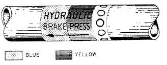
Figure 6-17.—Fluid line identification application.
stainless steel tubing currently installed on naval
aircraft need not be removed. The basic reason for
this is that cracked or damaged paint systems
establish a differential oxygen concentration cell,
which may result in tubing corrosion damage.
Do not paint interior surfaces of airspeed
indicator tubing, oxygen, or other plumbing lines.
Tube assemblies located inside of an aircraft are
interior tube assemblies. Tube assemblies located
outside of an aircraft are exterior tube assemblies.
Interior tube assemblies require a protective finish of
two coats of zinc chromate, using application
techniques as specified in Aircraft Weapons System
Cleaning and Corrosion Control, NA 01-1A-509.
Protective finishes for exterior tube assemblies should
be the same as for exterior aircraft surfaces specified
in NA01-1A-509.
and all others where tapes should not be used, painted
identification is applied to the lines.
Identification tape codes indicate the function,
contents, hazards, direction of flow, and pressure in
the fluid line. These tapes are applied in accordance
with MIL-STD-1247C. This military standard was
issued to standardize fluid line identification
throughout the Department of Defense. Figure 6-17
shows the method of applying these tapes as specified
by this standard.
The function of a line is identified by use of a
tape, approximately 1 inch wide, upon which word(s),
color(s), and geometric symbols are printed.
Functional identification markings, as provided in
MIL-STD-1247C, are the subject of international
standardization agreements. Three-fourths of the
total width on the left side of the tape has a code color
or colors that indicate one function only per color or
colors. The function of the line is printed in English
across the colored portion of the tape. Even a
non-English-speaking person can troubleshoot or
maintain the aircraft if he/she knows the code but
cannot read English. The right-hand one-fourth of the
functional identification tape contains a geometric
design rather than the color(s) or word(s).
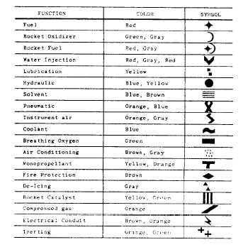
Figure 6-18 is a listing, in tabular form, of functions
and their associated identification media as used on
IDENTIFICATION
Fabricated tube assemblies should be identified
before installation or storage. All information from
the identification tag of the removed tube assembly
should be transferred to the tag on replacement tube
assembly. Identify the tube assemblies by ink
stamping or stenciling the part number, manu-
facturer’s code, and other required data on tube
assemblies. Apply a protective coat of clear varnish
over the markings. To aid in the rapid identification
of the various tubing systems and operating pressure,
each fluid line in the aircraft is identified by bands of
paint or strips of tape around the line near each fitting.
These identifying media are applied at least once in
each compartment. Various other information is also
applied to the lines.
Identification tapes are applied to all lines less
than 4 inches in diameter except cold lines, hot lines,
lines in oily environment, and lines in engine
compartments where there is a possibility of the tape
being drawn into the engine intake. In these cases,
Figure 6-18.—Functional identification type data.
6-16


