between the teeth is displaced into the outlet port.
This action produces a positive flow of fluid under
pressure into the pressure line. A shear pin or shear
section that will break under excessive loads is
incorporated in the drive shaft. This is to protect the
engine accessory drive if pump failure is caused by
excessive load or jamming of parts.
All gear-type pumps are constant displacement
pumps.
These pumps are usually driven by a dc
wound electric motor. For those aircraft using
batteries, the pump may be used to build up hydraulic
pressure for the brake system during towing
operation.
Maintenance of a pump at the organizational level
consists of replacement of the complete assembly.
The motor and pump may be ordered separately;
however, this is normally done by intermediate- and
depot-level maintenance only.
Removal and installation procedures are found in
the applicable MIM.
The following removal
procedures are typical examples.
1.
2.
3.
4.
5.
6.
Relieve reservoir pressure.
Pull the pump circuit breaker and place a
warning card, DO NOT OPERATE, on the
pump switch.
Disconnect the pump motor electrical
connection at the motor.
Drain the pump reservoir or cap the reservoir
suction line.
Disconnect the drain line at the pump.
Loosen the pressure and suction lines “B”
nuts.
7.
8.
9.
Remove the mounting screws/bolts that secure
the pump assembly to the aircraft structure.
Disconnect completely the pressure and
reservoir suction lines at the pump.
Cap all open lines, and lift the pump assembly
out of the aircraft.
The following installation procedures are typical
examples:
1.
2.
3.
4.
5.
6.
Place the pump on the aircraft structure
mounting pad.
Connect the pressure and
suction lines to the pump ports and tighten the
“B” nuts fingertight.
Align and install the mounting screws/bolts.
Tighten the “B” nuts to the correct torque
values.
Attach the electrical connection to the motor.
Service the reservoir to the proper level.
Perform operational check according to the
applicable MIM.
NOTE: Prior to the installation of hydraulic
units, the preservation fluid must be drained
and the unit flushed with clean hydraulic
fluid.
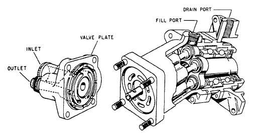
PISTON-TYPE PUMP (CONSTANT DIS-
PLACEMENT).—Piston-type constant displace-
ment pumps consist of a circular cylinder block with
either seven or nine equally spaced pistons. Figure
7-15 is a partial cutaway view of a seven-piston pump
manufactured by Vickers, Incorporated.
Figure 7-15.—Partial cutaway view of piston-type pump.
7-15


