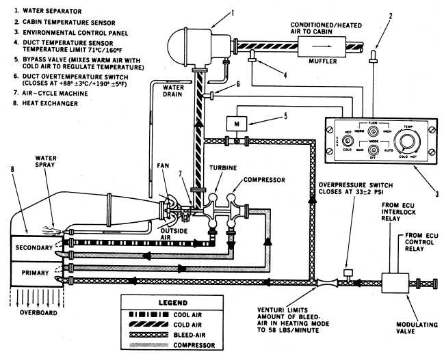
Figure 3-19.—Environmental control system.
of bleed air—engine and auxiliary power unit
(APU). The energy extracted from bleed air is
used to drive the ACM’s cooling fan and
compressor. Bleed air is applied to the ACM
through a modulating valve, which functions as
both an on/off valve and pressure regulator. Air
source selection is accomplished by means of the
AIR SOURCE ECS/START switch on the
overhead control panel. In the ENGINE position,
the engine bleed air is selected as a source. In APU
position, APU bleed air is used as the air source.
With ECS selected ON (from engine source),
maximum torque available is reduced by 3.5
percent.
An overpressure switch, located on the ACM
side of the modulating valve, senses high air
pressure. In an overpressure condition, the over-
pressure switch illuminates an advisory panel light
to indicate ECS HI PRESS. System shutdown
does not occur during an overpressure, since the
ACM is capable of withstanding full bleed-air
pressure, delivered by the engines or APU. Power
is supplied from the No. 2 ac primary bus and
the No. 2 dc primary bus, through two circuit
breakers, both on the sensor operators (SO)
circuit breaker panel, marked ECS PWR and ECS
CONTR, respectively. If ECS fails, cooling air
must be introduced into the nose avionics
compartment by pulling the nose door cooling
damper control located on the left-hand side of
the console.
ECS CONTROL PANEL
The ECS control panel contains a three-
position toggle switch to control the ECS
operating modes. At OFF, the switch provides the
power to shutoff the system for heating and
3-29