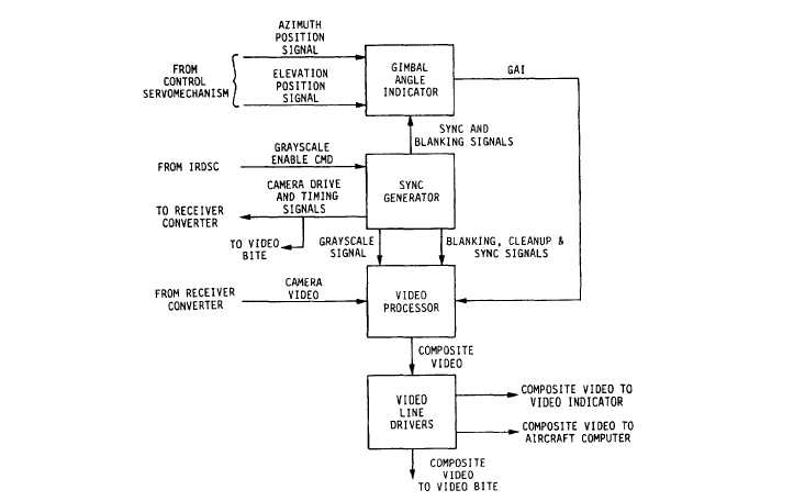
Figure 6-17.-Video converter video processing block diagram.
Figure 6-17 is a simplified block diagram of the
video processing sections found in a typical FLIR
power supply-video converter WRA. The gimbal
angle indicator unit receives linear signals from the
control servomechanism azimuth and elevation
gimbal potentiometers. These potentiometers
receive inputs from the gimbals in the
receiver-converter.
The potentiometers then
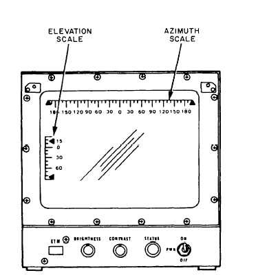
generate synthetic video signals. The signals
present short, bright-line segments along the
calibrated scales on the video indicator to show
receiver head position. An example of this is shown
in figure 6-18.
The sync generator module contains a
crystal-controlled clock. The module generates all
timing (sync), clamping, and drive signals for the
receiver-converter and the TV camera. It also
generates all timing, gating, clamping, and blanking
signals for the video processor and gimbal angle
Figure 6-18.-Azimuth/elevation scale on a video indicator.
6-15


