clamping signals from the sync generator. The video
processor combines all of these signals into a
composite video signal, which is fed to the video line
drivers. The video line drivers amplify the composite
video and provide three separate outputs. One output
goes to the video indicator, one goes to the aircraft
computer, and one goes to the video BITE module.
BITE Subsystem
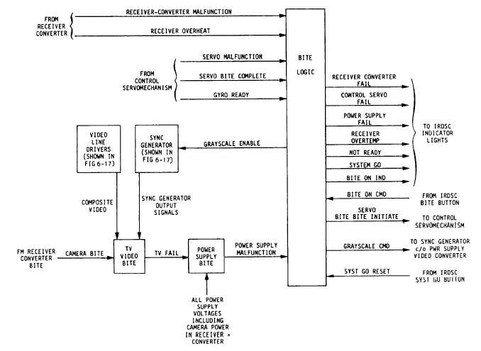
Figure 6-20 shows a simplified block diagram of
the BITE subsystem of the power supply-video
converter.
The BITE logic module receives an
initiation command signal from the IRDSC. This
command is generated whenever BITE is selected on
the IRDSC. The signal causes the BITE logic module
to generate and send a gray scale enable signal to the
sync generator. This signal overrides the gray scale
switch on the IRDSC, and causes the sync generator
to output a gray scale signal in addition to the sync,
blanking, clamping, and drive signals. BITE logic
also sends a BITE initiate signal to the control
servomechanism to initiate servo BITE. A BITE ON
signal is sent to the IRDSC from the BITE logic
module to light the BITE ON indicator. This indicator
shows that the BITE mode is operating.
The TV video BITE module monitors the output
of the sync generator, the video line drivers, and the
camera BITE from the receiver-converter. If a failure
occurs in any of these circuits, the video BITE module
generates and sends a TV fail signal to the power
supply BITE module.
The power supply BITE module monitors all of
the power supply voltages. If any voltage is not
correct, a power supply malfunction signal is
generated and sent to the BITE logic module. This
signal causes the logic module to send a power supply
fail signal to the IRDSC to light the power supply fail
light. If the power supply receives a TV fail signal
Figure 6-20.-Power supply-video converter BITE block diagram.
6-17


