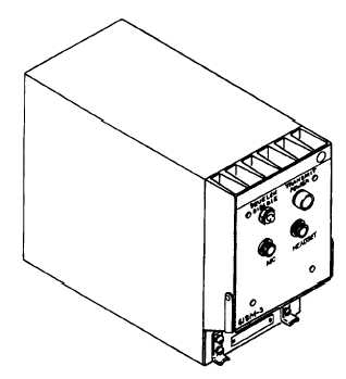
Figure 1-6-RT-1397/ARC-197 transceiver.
In the P-3C aircraft, this system interfaces with four of
the intercommunication stations in the transmit/receive
functions. The pilot, copilot, TACCO, and NAV/COMM
stations can transmit and receive over this radio. The
other stations in the aircrafl have receive function only.
MAJOR COMPONENTS
There are three components to the AN/ARC-197
system. These components are the RT-1397/ARC-197
transceiver, the C-11067/ARC-197 VHF-AM control
panel, and the 949880 VHF antenna.
RT-1397/ARC-197 Transceiver
The RT-1397/ARC-197 transceiver (fig. 1-6) is a
solid-state unit, consisting of a power supply, frequency
synthesizer, receiver modulator, and transmitter. There
is one indicator, one push button, one microphone jack,
and one headphone jack on the unit. The indicator is
labeled TRANSMIT POWER, which illuminates when
output power is greater than 10 watts. The push button
is labeled SQUELCH DISABLE, which will disable the
squelch for low signal levels. The microphone and
headphone jacks are used for maintenance and
emergency VHF communication in case of ICS failure
in-flight.
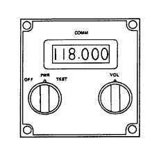
C-11067/ARC-197 VHF-AM Control Box
The control box (fig. 1-7) controls the operation of
the system. There are two dual function knobs and a
display window on the control panel. The display
window shows the selected frequency of the system.
Figure 1-7.-VHF-AM control box.
The outer ring of the dual function knob on the left
applies system power and selects the test function. The
inner knob changes the frequency of operation in
1-MHz steps over the range of control. The outer ring
of the dual function switch on the right is labeled VOL,
and it is not used in the P-3 aircraft. Volume is controlled
by the ICS system. The inner knob of this control is used
to change the frequency of operation in 25-kHz steps
over the range of control.
949880 VHF Antenna
The 949880 antenna is located in the tailcap on top
of the vertical stabilizer of the P-3 aircraft. This antenna
radiates and receives the VHF radio frequency signals.
Signals routed to and from the antenna go through a
VHF bandpass filter, which reduces the crosstalk
between the VHF and UHF systems.
VHF FUNCTIONAL DESCRIPTION
There are two modes of operation with the
AN/ARC- 197 radio. These two modes are receive and
transmit.
Receive Mode
In the receive mode, the received RF signals from
the antenna are routed through the filter, and applied to
the receiver circuits in the transceiver. The frequency
selected on the control box is applied to the frequency
synthesizer. The synthesizer uses a single phase-locked
loop to generate RF injection frequencies, in 25-kHz
steps, from 116.000 to 155.975 MHz. The RF injection
frequencies, along with dc tuning voltages,
electronically tune the receiver to the selected
frequency. The AM detected audio is applied to the
audio amplifier circuit. Squelch circuits disable the
output amplifier if the required signal-to-noise ratio or
carrier level is not present. The output audio is then
applied to the ICS interconnection box for distribution
to the various stations.
1-12