
CAUTION
fig. 5-3) to straighten the contacts. Using any other tool
could cause further damage to the relay. This could
Do not use files, sandpaper, or emery cloth to clean
result in your having to replace the entire relay.
the contacts as these materials will damage the contacts
and leave metal particles or debris in the equipment.
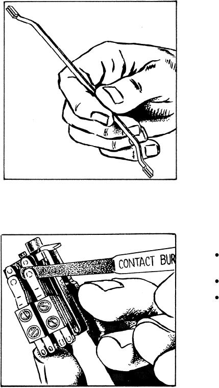
If a film buildup is visible on the contact surfaces of
a relay, the contacts require cleaning. You should use a
CONVERTER/INVERTER ASSEMBLIES
burnishing tool, such as the one shown in figure 5-4, to
clean the contacts. When you clean relay contacts, be
Dc/dc converters produce the dc voltages required
careful to avoid altering the shape of the contacts.
to operate the circuits of the ship's control equipment
system. Each different voltage level requires a separate
dc/dc converter. Many of the electronic enclosures and
consoles on gas turbine ships contain
converters/inverters. The basic configuration of all the
dc/dc converters is the same. The differences exist in the
final output transformer and the associated faltering
components.
Maintenance Requirements
Once
installed in
the
equipment,
converters/inverters require minimum maintenance. As
with all transistorized units, heat is the major problem.
Preventive maintenance is limited to cleaning and
periodic adjustments. Corrective maintenance requires
the use of specific test equipment and procedures
outlined in technical manuals.
Symptoms of Overheating
During preventive maintenance, you should check
Figure 5-3.--Point bender.
f o r conditions that indicate overheating of the
converter/inverter. Make certain to observe all standard
electrical safety precautions when replacing or repairing
converter/inverters. The following conditions usually
indicate overheating of a converter/inverter:
Charred or burned insulation on the
converter/inverter
Darkened or charred resistors and transistors
Excessively hot components
CONTROL CIRCUITS
The
operation of many of the engineering systems
depends
on effective operation of the control circuits. In
fact, all
electrical systems and equipment are controlled
in some
manner by one or more controls.
Checking and Adjusting Set Points
Figure 5-4.--Burnishing tool.
Control circuits should be checked regularly for
circuit continuity and proper relay, switch, or indication
5-6