
performing this procedure, be careful to ensure that a
troubleshooting, maintenance, and repair of these
components. In this section, we will briefly describe
short wire from one side of the cable being spliced is
connected to a long wire from the other cable. Make
these areas.
certain the sharp ends are then clamped firmly down on
Inspection and Troubleshooting
the conductor. The figure shows a Western Union splice
being staggered.
In the maintenance of cables and connectors, the
first consideration is a thorough visual inspection. This
Fabrication Procedures
check should reveal such defects as corrosion, chafing,
loose connections, broken wires, evidence of
As a GSE, you must learn to fabricate a cable using
overheating, and mismated connectors. You can make
connectors. The type of connector you must use is
additional checks to be sure there are no open or shorted
specified in the service and overhaul instructions for the
conductors in the cable. Usually, you will use an
particular equipment.
ohmmeter to perform these checks.
To fabricate a cable, use the following steps:
1. Disassemble the connector to allow access to the
CAUTION
contacts. Devise a means of holding the connector so
Many ohmmeters are supplied with test leads that
you will have both hands free. (A small bench vise is
are slightly larger than the female sockets used in
useful for this purpose.)
c o n n e c t o r s . Forcibly inserting these probes can
2. Cut the cables to the correct length,
irreparably damage the sockets. Exercise care to prevent
such damage.
3. Strip the wire ends with a wire stripper or knife.
If you use a knife, avoid cutting or nicking the wire
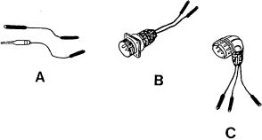
In reference to the caution, most GSEs make pin
strands.
testers. Some examples of pin testers are shown in figure
5-12. A pin tester is a device constructed of the pins and
4. Tin the bare wire ends.
receptacles of cannon plugs (view A). The pin tester can
5. Run the wires through the connector assembly
also be a complete replacement cannon plug that has the
and coupling nuts.
electrical cable attached and the ends of the individual
wires exposed (views B and C). A pin tester can help
6. See that all surfaces are clean.
you prevent short circuits or incorrect readings caused
7 . Flow rosin-core solder into the connector
terminals.
the readings from the cannon plugs. The test leads can
8. Insert each wire into its terminal by holding the
slip off the pin of the cannon plug and short circuit to
tip of the soldering iron against the terminal. As the
the other pins. This could result in serious damage to the
solder melts, push the wire into the cavity, and then hold
cannon plug or the equipment. Make certain you follow
the wire steady while the solder cools.
all applicable electrical safety precautions when using
fabricated pin testers.
CAUTION
Be careful to avoid damaging the connector
insulation with the soldering iron. When you solder the
connector, the recommended sequence is to start from
the bottom connection and work from left to right,
m o v i n g up a row at a time. After soldering the
connections, solder the shields (if used) to a common
terminal on a ferrule. Then lace the cable and reassemble
and moistureproof the connector, if necessary.
INSPECTION, MAINTENANCE, AND
REPAIR PROCEDURES
Figure 5-12.--Fabricated pin testers.
Routine maintenance of electrical connectors and
m u l t i c o n d u c t o r cables involves the inspection,
5-11