cable. Multiconductor cables consist of any number of
individual conductors. This number ranges from as few
as 2 conductors to as many as 36 conductors.
Splicing Requirements
Some electrical components on gas turbine ships are
located in areas where they are subjected to salt spray,
oil, and water. These conditions can cause connections
to corrode and conductors to break To connect these
c a b l e faults, the GSE must know how to splice
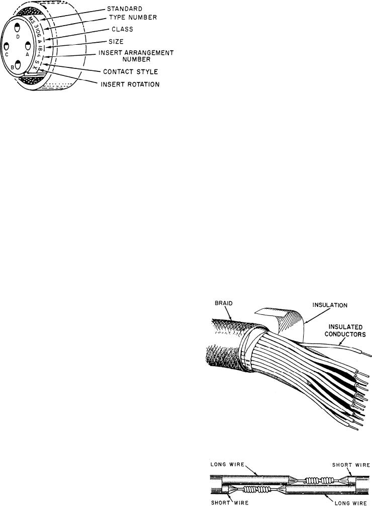
Figure 5-9.--MS connector marking.
multiconductor cables properly.
Conductor splices are an essential part of any
electric or electronic circuit. Any electric or electronic
2. The type number indicates the type of shell.
circuit is only as good as its weakest link. The basic
3. The class letter indicates the design of the shell and
r e q u i r e m e n t of any splice is that it be both as
the purpose for which the connector is normally used.
mechanically and electrically sound as the conductor or
device with which it is used. Quality workmanship and
4. The size number indicates the shell size. This
proper materials will ensure lasting electrical contact
size is either the outside diameter of the mating part of
and physical strength.
the insert or the diameter of the coupling threads (in
sixteenths of an inch).
J o i n i n g small, multiconductor cables together
presents somewhat of a problem. Each conductor must
5. The insert arrangement number indicates the
be spliced and taped. If the splices are directly opposite
arrangement of the contacts in the insert but not the
each other, the overall size of the joint becomes large
number of contacts.
and bulky. You can create a smoother and less bulky joint
6. The contact style letter indicates that the contacts
by staggering the splices.
are of two styles: socket (female), shown by the letter
Figure 5-11 shows how a two-conductor cable is
S; or pin (male), shown by the letter P.
joined to a similar cable by staggering the splices. In
7. The insert rotation letter indicates an alternate
insert position. Insert rotation letters W, X, Y, or Z
indicate that the insert has been rotated (with respect to
the shell) a specified number of degrees from the normal
position. If the insert is in the normal position, no letter
is used.
F o r more detailed information on types and
designations of connectors, refer to H a n d b o o k o f
I n s t a l l a t i o n Practices for Aircraft Electric and
Electronic Wiring, NAVAIR 01-1A-505.
MULTICONDUCTOR CABLES
Engineering electrical and electronic systems
require a large variety of electrical cables. Some circuits
Figure 5-10.--Multiconductor cable.
require only a few conductors having a high current
capacity. Other circuits require many conductors having
a low current-carrying capacity. A GSE must learn the
proper techniques used in cable maintenance.
The engineering control systems on gas turbine
ships consist primarily of multiconductor cables. These
cables connect the operating consoles to the respective
Figure 5-11.--Staggering splices.
equipment. Figure 5-10 is an example of a multiconductor
5-10

