
measure of a parameter that may vary over a period of
c o n t r o l and monitoring units. A dual-stage DMS
configuration is used on the DDG-51 class ship. The
time (speed in rpms, temperature in degrees). The
following types of sensors are used on the DDG-51 class
term dual-stage indicates that multiplexing occurs in
two stages. The first stage is done in the remote
ships:
multiplexer, while the second stage is done in the area
1. Contact sensors
m u l t i p l e x e r . The DMS converts signals suited to
2. Tank level sensors
machinery monitoring and control to signal types best
suited to high-speed communications.
3. Temperature sensors
4. Pressure sensors
MCS COMPUTER PROGRAM
FUNCTIONS
5. Tachometer/frequency sensors
6. Ship's service electrical distribution sensors
Each MCS console computer on a DDG-51 class
Signal conditioners external to the MCS provide the
s h i p is programmed with common and specific
control and monitoring interface between a GTE and the
functions. The common functions are the general MCS
SCU, and between a SSGTG and the EPCC. Signal
console and the EOOW/LU operating functions. The
conditioners on the bottom of the GTE provide analog
specific functions relate to the control and monitoring
inputs to an interim integrated electronic control (IIEC).
of the engineering plant equipment assigned to a specific
The IIEC processes and conditions the GTE parameter
console. In this section, we will discuss briefly the
inputs to the SCU in its MER. The IIEC analog outputs
methods used by the MCS and the GSEs to test the
range from 0 to 10 volts dc. The IIEC discrete outputs
e n g i n e e r i n g control system. For a more detailed
are either 0 volts dc or +10 volts dc.
description of the test and calibration procedures
required to maintain the MCS equipment, refer to the
Signal conditioners in the SSGTG local control
appropriate technical manuals.
panel (LOCOP) provide analog inputs to a micro-
processor inside the LOCOP. The LOCOP processes
Self-Test Program
and conditions SSGTG inputs and provides a set of
outputs to the EPCC. The LOCOP analog outputs range
The self-test function provides testing of major
from 4 to +20 milliamps. The LOCOP discrete outputs
components in a console during unit initialization, after
a r e microprocessor-controlled relay contact state
a system reset, and about twice each second during
changes (open/close).
normal operation. The self-test function carries out the
computer and peripheral automatic tests. The test results
Serial and Parallel Data Communication
are placed in the console computer database for display
on the PDU when requested by the GSE.
Interconsole and intraconsole information ex-
changes are in the form of binary signals. These signals
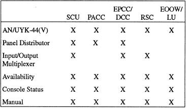
Test Functions
are discrete signals, characterized by high and low
voltage levels. These voltage levels represent conditions
The self-test functions at each console are
such as on/off, opened/closed, or digitized analog data.
summarized in table 3-1.
The signals are arranged in groups or arrays known as
data words. Each binary signal within the data word is
Table 3-1.--MCS Console Self-Tests
called a data bit and has a binary zero or a binary one
logic value. The number of data bits contained in a data
word is called the word bit length. The data words can
be exchanged in a parallel or a serial format. Data is sent
and received by the same methods we described for the
DD-963 and CG-47 class ships.
DMS
The AN/USQ-82F(V) DMS is a dedicated signal
processing and high-speed serial data transmission
system. It is composed of interconnected data flow
3-9