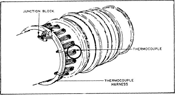
For instructions on thermocouple replacement,
monitored. Figure 5-9) shows the thermocouple
refer to the appropriate manufacturers' technical
installation on the Allison 501 - K17.
manuals.
The interconnecting harness for the thermo-
couples, as shown in figure 5-9, mounts on the
TEMPERATURE SWITCHES
outer combustion case forward of the ther-
mocouples. This harness includes four separate
Temperature switches operate from tempera-
leads for each of the eighteen sensors. Two
ture changes occurring in an enclosure, or in the
separate electrical circuits arc maintained. The
air surrounding the temperature sensing element.
harness is made in two halves, a right-hand side
The operation of the temperature switch is not
and a left-hand side. Note in figure 5-9 that the
much different than that of the pressure switch.
harness is split near the thermocouple junction.
Actually, both switches are operated by changes
This allows you to easily remove the wiring
in pressure. The temperature element is arranged
without major engine disassembly. The electrical
so changes in temperature cause a change in the
signals from the thermocouples are averaged
internal pressure of a sealed-gas or air-filled bulb
within the harness. The output of the thermo-
or helix, which is connected to the actuating device
couple harness is sent to the local operating panel
by a small tube or pipe. Figure 5-10 shows you
(LOCOP) for signal conditioning.
a temperature switch and two types of sensing
A faulty thermocouple will give you a false
elements.
TIT reading. The TIT is a basic parameter for the
liquid fuel valve (LFV) adjustment. Therefore, a
Construction
faulty sensor would result in an incorrectly
adjusted LFV. You should check the continuity.
You can connect the bulb and helix units to
of the thermocouples if you suspect the TIT
the switch section. The bulb unit (fig. 5-10,
reading is incorrect. Also, check it if you suspect
item A) is normally used when you need to control
the LFV is out of adjustment. The thermocouple
liquid temperatures. However, it may control air
continuity is read with an ohmmeter. Each ther-
or gas temperatures. This only happens if the
mocouple has four terminals, but only two are
circulation around it is rapid and the temperature
used for monitoring TIT. Find the two terminals
changes at a slow rate.
that are used for TIT and read the resistance
The helical unit (fig. 5-10, item B) has been
between them. If the reading on a thermocouple
specifically designed for air and gas temperature
is over 10 ohms, you must replace that sensor.
Figure 5-9.--Allison 501-K17 thermocouple harness.
5-8

