
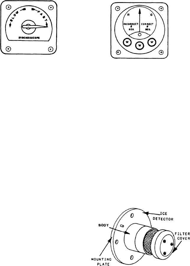
Figure 5-28.--Synchroscope.
Figure 5-29.--Phase-sequence indicator.
constantly. The speed of rotation is equal to the
difference in frequency; the direction shows
when the temperature falls below 41F and the
whether the generator is fast or slow. The
relative humidity is above 70 percent. The
generator is placed on line when the pointer slowly
formation of ice in the inlet has two detrimental
approaches a mark. This mark shows that the
effects. It can restrict airflow to the gas turbine
generator and bus-bar voltages are in phase.
with a resultant loss of power. Also, if allowed
to build up in large quantities, ice chunks can
PHASE-SEQUENCE INDICATORS
break off. They can go through the gas turbine
The sequence in which the currents of a
compressor causing foreign object damage (FOD).
3-phase system reach their maximum values
The ice detector sensor is located in the lower
is determined by phase-sequence indicators.
left corner of the inlet barrier wall. It senses
Figure 5-29 shows an example of this type of
inlet temperature and humidity and transmits
indicator.
proportional electrical signals to the signal
Gas turbine ships have phase-sequence
conditioner. The signal conditioner is mounted
indicators installed in switchboards which may be
on the underside of the base. It provides a signal
connected to shore power. These instruments
for the icing alarm at the propulsion console when
indicate whether shore power is of correct or
icing conditions exist.
incorrect phase sequence before shipboard equip-
ment is connected to shore power. Three-phase
Ice Detectors
motors, when connected to incorrect phase-
sequence power, rotate in the opposite direction.
The detector shown in figure 5-30 consists of
The phase-sequence indicator has three neon
a sensor assembly mounted in a body secured to
lamps that light when all three phases are
energized. A meter connected to a network of
resistors and condensers shows correct or in-
correct sequence on a marked scale.
MISCELLANEOUS SENSORS
Several of the sensors used in the gas turbine
propulsion plant are not pressure or temperature
sensors. These devices, such as ice detectors,
speed sensors, vibration sensors, and UV flame
detectors, are used to monitor or protect the gas
turbine plant from damage.
ICE DETECTOR SYSTEM
Under certain atmospheric conditions, ice can
form in the inlet airflow system. This can happen
Figure 5-30.--Ice detector.
5-21