
A diagram for shore services connection
Stage II deals with the system component level
locations. This diagram delineates the location of
under supervision of the space supervisor in each
shore service connections for steam, electrical
engine room (ER) and auxiliary machinery room
power, feedwater, potable water, firemain, and
(AMR), and the electric plant control console
fuel oil.
(EPCC) operator (EPCC watch). In stage II, the
space supervisor accomplishes the tasks delegated
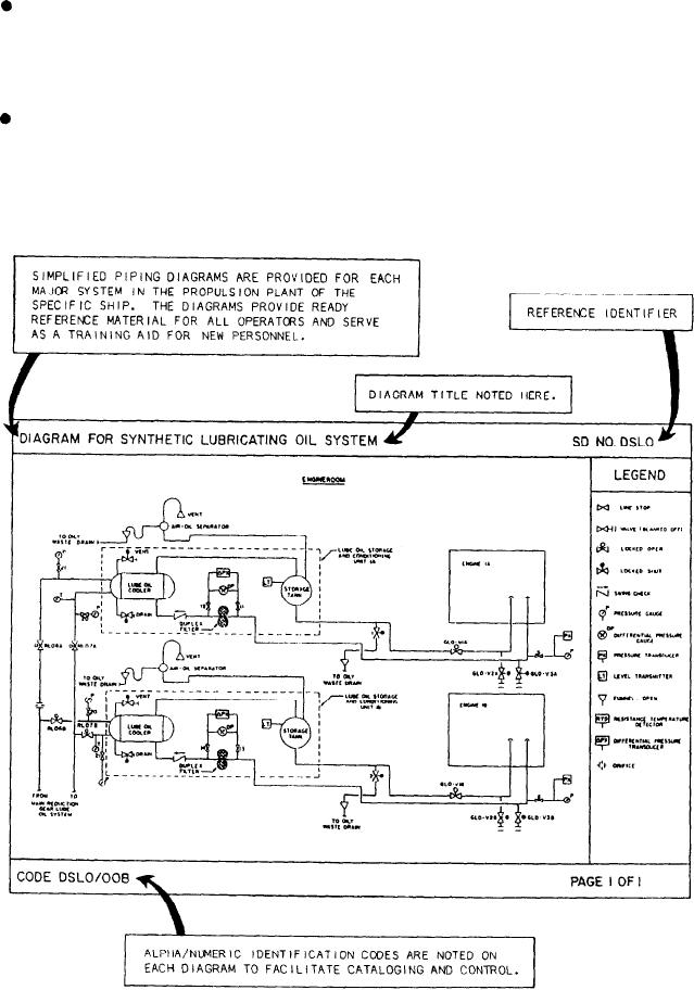
Training diagrams (fig. 2-13) delineating
by the plant supervisor. The EOP documentation
each major piping system to aid in plant
assists the space supervisor in properly sequencing
familiarization and training of newly assigned
events, controlling the operation of equipment,
personnel. These diagrams indicate the relative
maintaining an up-to-date status of the opera-
locations of lines, valves, and equipment.
tional condition of the equipment assigned, and
Figure 2-13.--Sample training diagram.
2-29