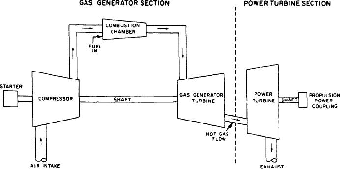
Figure 1-21.--Split-shaft engine.
The short length of the can-annular type of
is connected directly to the same turbine rotor that
chamber provides minimal pressure drop of the
drives the compressor. Usually, a speed decreaser
gases between the compressor outlet and the flame
or reduction gear is located between the rotor and
area. The relatively cool air in the annular outer
the power output shaft. A mechanical connection
can reduces the high temperatures of the inner
still exists throughout the engine.
cans. This air blanket keeps the outer shell of the
combustion section cooler. Maintenance on the
In the split-shaft engine (fig. 1-21), no
burners is simple. You can remove and inspect
mechanical connection exists between the GG
any number of burners just by sliding the case
turbine and the PT. In this type of engine, the
back.
output speed is varied by variation of the
generator speed. Also, under certain conditions,
the GG can run at a reduced rpm and still provide
CLASSIFICATION BY
maximum PT rpm. The reduced rpm greatly
improves fuel economy and also extends the life
TYPE OF SHAFTING
of the GG turbine. The starting torque required
Several types of GTE shafts are used. These
is lowered because the PT, reduction gears, and
are single shaft, split shaft, and twin spool. Of
output shaft are stationary until the GG reaches
these, the single shaft and split shaft are the most
approximate idle speed. Another feature of the
common in use in naval vessels. The twin-spool
multishaft marine propulsion plant is the GG
-shaft is currently used for marine military applica-
rotates only one way. One design (clockwise
tion only on the U.S. Coast Guard Hamilton class
rotation or counterclockwise rotation) of the GG
cutters, which use the Pratt-Whitney FT-4 twin-
can be used on either shaft and still allow the PT
spool GTE.
to rotate either way. This is done by changing the
In current U.S. Navy service, the single-shaft
PT wheel and nozzles. The arrangement shown
engine is used primarily for driving ship's service
in figure 1-21 is typical for propulsion GTEs
generators. The split-shaft engine is used for main
aboard today's ships.
propulsion, as a variety of speed ranges is
encountered.
The twin-spool type of GTE is sometimes
referred to as a multistage GTE. It has two
Figure 1-20 is a block diagram of a single-shaft
GTE. In the engine shown, the power output shaft
separate compressors and two separate turbine
1-19

