
Figure 1-24.--Turbine rotor elements.
Figure 1-23.--Cutaway view of a turbine stator.
nozzle converts a varying portion of the heat and
pressure energy to velocity energy. The velocity
energy can then be converted to mechanical energy
through the rotor blades.
The turbine nozzle functions to deflect the
gases to a specific angle in the direction of
turbine wheel rotation. The gas flow from the
nozzle must enter the turbine blade passageway
while it is still rotating, making it essential
to aim the gas in the general direction of turbine
rotation.
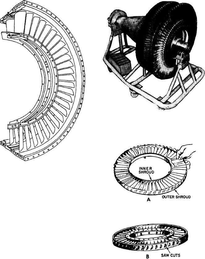
The turbine nozzle assembly has an inner
shroud and an outer shroud between which
are fixed the nozzle vanes. The number of
Figure 1-25.--Turbine nozzle assemblies. A. Loose-fitting
vanes varies with different types and sizes
vanes. B. Welded vanes.
of engines. Figure 1-25 shows typical turbine
nozzle assemblies.
1-21