
Figure 1-31.--GG turbine rotor blade cooling.
Power Turbines
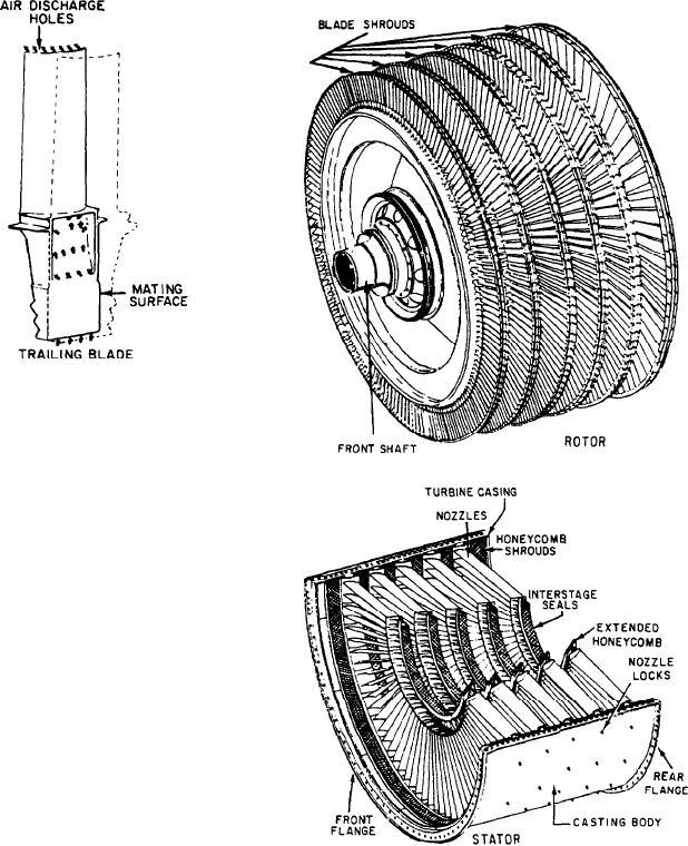
The PT (fig. 1-32) is a multistage turbine
located behind the GG turbine. The two turbines
have no mechanical connection between them.
The PT is connected to a reduction gear through
a clutch mechanism. Either a controllable
reversible pitch (CRP) propeller or a reverse gear
is used to change the direction of the ship.
Power turbines are used to extract the
remaining energy from the hot combustion gases.
They extract this energy in the following three
ways, depending upon engine application:
1. The aircraft power turbine is designed so
the turbine extracts only enough energy from the
gases to run the compressor and accessories.
2. In the solid-wheel turbine (used primarily
in small GTEs), as much energy as possible is
extracted from the gases to turn the turbine. The
turbine provides power for the compressor,
accessories, and the airplane propeller or the
ship's generator. These engines are designed to
run at 100 percent specified rpm all the time. The
Figure 1-32.--Typical power turbine.
location of the mechanical connection between the
turbine wheel and the reduction gear on the
compressor front shaft depends on the design of
3. Marine propulsion engines use a combina-
the installation. Normally, a ship's service
tion of the previously mentioned two turbine
generator cannot be disconnected from its GTE
types. The GG has a single- or multiple-stage HP
except by disassembly. This setup is used for
rotor that drives the compressor and accessories
generators to prevent slippage between the engine
and an LP turbine to transmit power to the ship's
and the generator.
propeller via the reduction gear and shafting.
1-25