
scavenge, and sump vent. We will discuss these
subsystems and their components in chapter 2.
Oil Seals
Three types of oil seals are common to the
GTEs, the lip-type seal, the labyrinth/windback,
and the carbon ring.
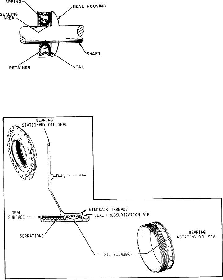
LIP-TYPE SEAL.--The lip-type seal (fig.
1-36) is used to prevent leakage in one direction
only. A metal frame is covered with a synthetic
material, usually neoprene. The neoprene is
somewhat smaller than the shaft. The elasticity
of the neoprene will allow the shaft to slide
through the seal. The seal is molded with a lip to
retain a spring around the center. The spring keeps
a snug fit around the shaft. The construction of
Figure 1-36.--Lip-type seal.
the lip-type seal allows for some very slight
misalignment and for axial movement of the
Figure 1-37.--Labyrinth/windback seal.
1-30