
shaft. The lip seals are used where relatively low
the carbon rings. The air pressure is forced out
speeds and temperatures are encountered.
along the shaft in both directions. The pressure
prevents oil from entering the compressor or
Two disadvantages of the lip-type seals are
turbine and combustion gases from reaching the
that (1) they will seal against only little or no fluid
pressure, and (2) they are easily damaged. A burr
bearings. The main disadvantage of this seal is
on the shaft or dirt can tear the seal and cause
minor oil leakage that occurs during start-up and
leakage.
run down as the oil pump moves oil before enough
airflow prevents leakage. However, the leakage
LABYRINTH/WINDBACK SEAL.--The
is so slight that the engine normally will reach its
designated overhaul hours of operation before oil
labyrinth/windback seals (fig. 1-37) combine a
rotating seal having oil slingers and a serrated
accumulation will have any effects.
surface with a stationary seal having windback
threads and a smooth rub surface. The oil slingers
STARTING SYSTEMS
throw oil into the windback threads, which direct
the oil back to the sump area. The serrations cut
The GTEs use a starter to turn the compressor
grooves into the smooth surface of the stationary
at sufficient speed to initiate and sustain
seal to maintain close tolerances throughout a
combustion. Both the compressor and the GG
large temperature range. This seal allows a small
turbine must spin. In starting dual axial-flow
amount of seal pressurization air to leak into the
compressor engines, the starter needs to rotate
sump, thereby preventing oil leakage.
only the HP compressor. The starter's first
requirement is to accelerate the compressor to
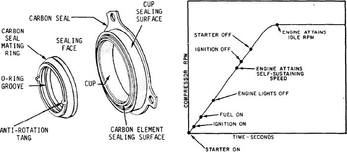
CARBON RING SEAL.--The carbon seal
provide enough airflow and pressure to support
(fig. 1-38) has a stationary, spring-loaded, carbon
combustion in the burners.
Once fuel has been introduced and the engine
sealing ring and a rotating, highly polished steel
mating ring. It prevents oil in the gearbox from
has fired, the starter must continue to accelerate
leaking past the drive shafts of the starter, fuel
the compressor above the self-sustaining speed of
pump, and auxiliary drive pad.
the engine. The starter must provide enough
Another form of the carbon seal is also in use.
The carbon rings are not spring-loaded. They
and air loads of the engine.
Figure 1-39 shows a typical starting sequence
move freely around the shaft and seal axially
against the housing. When the engine is up to
for a GTE. When the starter has accelerated the
speed, the rings center themselves radially in the
compressor enough to establish airflow through
housing. Compressor bleed air is forced between
Figure 1-39.--Typical starting sequence for a GTE.
Figure 1-38.--Carbon ring seal.
1-31