
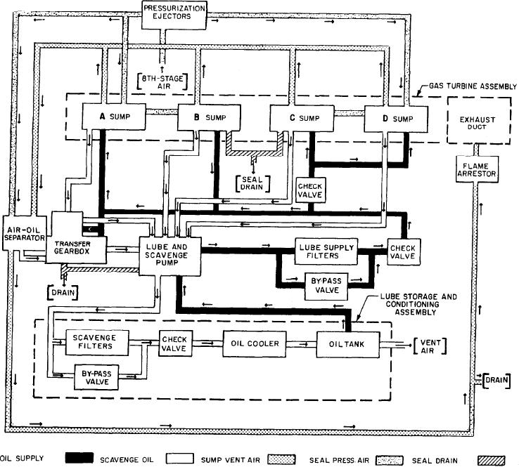
Figure 1-35.--Lubrication system schematic (typical).
of lube oil to the bearing at all engine speeds. This
and the splines. Separate scavenge elements in the
is sometimes known as a calibrated oil system.
lube and scavenge pump remove oil from the
Since lube oil is supplied to the various parts of
sumps and the transfer gearbox (accessory drive).
the system under pressure, provision is made to
prevent the oil from leaking into unwanted areas,
The scavenged oil is returned to the lube storage
such as the compressors and turbines. This is
and conditioning assembly where it is filtered,
usually accomplished by use of lip-type seals,
cooled, and stored. Scavenge oil is filtered by a
duplex filter mounted on the lube storage tank.
labyrinth oil seals, or carbon ring pneumatic oil
seals. We will discuss these seals in detail later in
this section.
Lubrication System Subsystems
The lubrication system provides the GTE
The lubrication system is usually divided into
three subsystems identified as lube supply, lube
oil to prevent excessive friction and heat. Oil
1-29