
shown in figure 1-28. The blades are retained in
their respective grooves by a variety of methods.
Some of the more common methods are pinning,
locking tabs, riveting, and retaining rings. Figure
1-29 shows a typical turbine wheel using riveting
for blade retention.
Turbine blades may be either forged or cast,
depending on the metal they are made of.
Turbine blades are usually machined from
individual forgings. Various materials are used in
the forging. Speed and operating temperatures are
important factors in deciding what materials go
into the turbine blades.
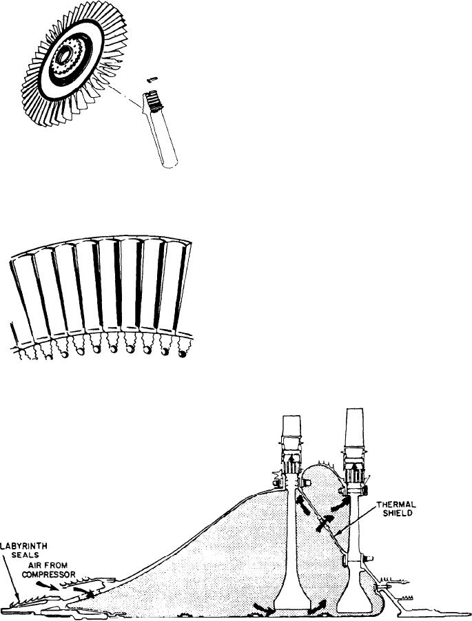
Large engines use an air-cooled blading
arrangement on the GG turbine (fig. 1-30).
Compressor discharge air is constantly fed
through passages along the forward turbine shaft
Figure 1-28.--Turbine blade with fir-tree design and tab lock
between a spacer and the shaft. A thermal shield
method of blade retention.
directs the cooling air along the face of the disk
to cool the disk. The shield is between the first-
and second-stage turbine wheels. The air is then
directed through slots in the fir-tree portion of
the disk, into slots in the blade fir-tree. The air
then goes up through holes in the blades to cool
the blades (fig. 1-31).
Cooling of the turbine wheel and blades
reduces thermal stresses on the rotating members.
The turbine nozzles are also air-cooled. By
cooling the stationary and rotating parts of the
turbine section, higher turbine inlet temperatures
are permissible. The higher temperatures allow for
more power, a more efficient engine, and longer
engine life.
Figure 1-29.--Riveting method of turbine blade retention.
Figure 1-30.--GG turbine rotor cooling airflow.
1-24