
All turbine nozzles must be constructed to
allow for thermal expansion, because rapid
temperature variances could cause distortion or
warping of the metal components. Thermal
expansion of turbine nozzles is allowed by one of
several construction methods.
In one method the vanes are assembled loosely
in the supporting inner and outer shrouds (fig.
1-25, view A). Each of the vanes fits into a
contoured slot in the shrouds. The slots conform
with the airfoil shape of the vanes. These slots
are slightly larger than the vane to give a loose
fit. For further support the inner and outer
shrouds are encased by an inner and an outer
support ring. This adds strength and rigidity to
the turbine nozzle. These supports also permit
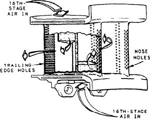
Figure 1-26.--First-stage GG turbine nozzle cooling.
removal of the nozzle vanes as a unit; otherwise,
the vanes could fall out of the shrouds as the
is directed to the nozzle. The air cools both the
shrouds are removed.
turbine (discussed later) and the nozzle. The
Another method to allow for thermal expansion
is to fit the vanes into inner and outer shrouds.
nozzle may also be cooled by air admitted from
the outer perimeter of the nozzle ring. The method
In this method the vanes are welded or riveted
of getting the air in is determined by the
into position (fig. 1-25, view B). Either the
manufacturer.
inner or the outer shroud ring is cut into
The nozzle vanes are made with many small
segments to provide for thermal expansion. The
holes or slots on the leading and trailing edges
saw cuts dividing the segments will allow enough
expansion to prevent stress and warping of the
(fig. 1-26). Air is forced into the nozzle and out
through the slots and holes. The vane is cooled
vanes.
as the air passes through. The air is discharged
The basic types of construction of nozzles are
into the hot gas stream, passing through the
the same for all types of turbines. The turbine
remainder of the turbine section and out the
nozzles are made of high-strength steel to
exhaust duct.
withstand the direct impact of the hot, HP, high-
Figure 1-27 shows temperature comparisons
velocity gases from the combustor. The nozzle
of a nornair-cooled vane and an air-cooled vane.
vanes must also resist erosion from the high-
Cooling air is used primarily in the HP turbine
velocity gases passing over them.
If the inlet gas temperature could be increased
section and not in the LP section. By the time the
by about 750F, almost a 100 percent increase in
gases reach the LP turbine section, the tempera-
ture of the gases is at an acceptable level. In the
specific horsepower could be achieved. Nozzles
LP turbine section, metals in current use will last
can not stand up for long to these higher
for a long time.
temperatures. Many different methods of in-
creasing nozzle endurance have been tried over
TURBINE ROTORS.--The rotor element of
the years. One method that was tried was to
the turbine consists of a shaft and bladed wheel(s).
coat the nozzle with ceramic. Higher temperatures
The wheel(s) is attached to the main power
were achieved, but the different expansion rates
transmitting shaft of the GTE. The jets of
of the steel and the ceramic caused the coating
combustion gas leaving the vanes of the stator
to break away after several hours of operation.
Experiments are still being conducted, even so far
element act upon the turbine blades, making them
rotate. The turbine wheel can rotate in a speed
as to use an entirely ceramic nozzle.
range of about 3,600 to 42,000 rpm. These high
Another means of withstanding high tempera-
rotational speeds impose severe centrifugal loads
tures is to use newly developed alloys. However,
on the turbine wheel. At the same time, the high
the extreme costs of the alloys prohibit commer-
cial production of such nozzles. Still another
temperatures (1050 to 2300F) result in a
lowering of the strength of the material. The
method, in wide use today in large engines, is to
engine speed and temperature must be controlled
use air-cooled nozzle vanes. Compressor bleed air
to keep turbine operation within safe limits.
is fed through passages to the turbine, where it
1-22