
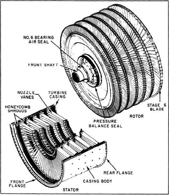
Figure 2-38.--LP turbine rotor and stator.
the GG. If the GG must be changed out, it is
first three stages of blades are coated for corrosion
simply unbolted from the PT and removed. If PT
protection.
replacement is required, the GG must be removed
also.
Stator
Rotor
The PT stator, also shown in figure 2-38, has
two casing halves (only the lower half is shown),
The PT rotor (fig. 2-38) has six disks with
the stage 2 through 6 turbine nozzles, and six
integral disk spacers bolted together to form the
stages of blade shrouds. The first-stage nozzle is
rotor spool. Blades of all six stages contain
part of the turbine mid frame. Honeycomb
interlocking tip shrouds for low vibration levels
shrouds, mounted in casing channels, mate with
and are retained in the disks by dovetails.
the shrouded blade tips to provide close-clearance
Replaceable rotating seals, secured between the
seals. These stationary interstage seals are
disk spacers, mate with stationary seals to
attached to the inner ends of the nozzle vanes to
prevent excessive gas leakage between stages. The
maintain low leakage between stages. Insulation
2-31