
support, the stage 1 and stage 2 turbine shrouds,
and the interstage seal. The nozzle support
is a conical section with a flange that is
bolted between the flanges of the compressor
rear frame and the turbine mid frame. The
support provides for the mounting of the nozzles,
the cooling air feeder tubes, and the stage 1
and stage 2 turbine shrouds. The nozzles are
cast and then coated to improve erosion and
oxidation resistance. The vanes (two per nozzle)
direct the gas stream onto the second-stage
turbine blades. The inner ends of the nozzles
form a mounting circle for the interstage seal
attachment. The turbine shrouds form a portion
of the outer aerodynamic flow path through the
turbine. They are located radially in line with
the turbine blades and form a pressure seal
to prevent excessive gas leakage over the blade
tips. The first stage has 24 shroud segments; the
second stage has 11 shroud segments. The inter-
stage seal is composed of six segments bolted to
the nozzles. Its purpose is to minimize gas leakage
between the second-stage nozzle and the turbine
rotor. The sealing surface is honeycomb and has
four steps for maximum sealing. Since the
honeycomb cools more rapidly than the four
rotating sealing teeth, the honeycomb is pre-
grooved to prevent contact under rapid or
emergency shutdown conditions. The second-
stage nozzle is air-cooled by convection. The
nozzle vane center area and leading edge are
cooled by 13th-stage air which enters through
cooling air tubes. Some of the air is discharged
through holes in the trailing edge; the remainder
flows out through the bottom of the vanes and
is used to cool the interstage seals and turbine
blade shanks.
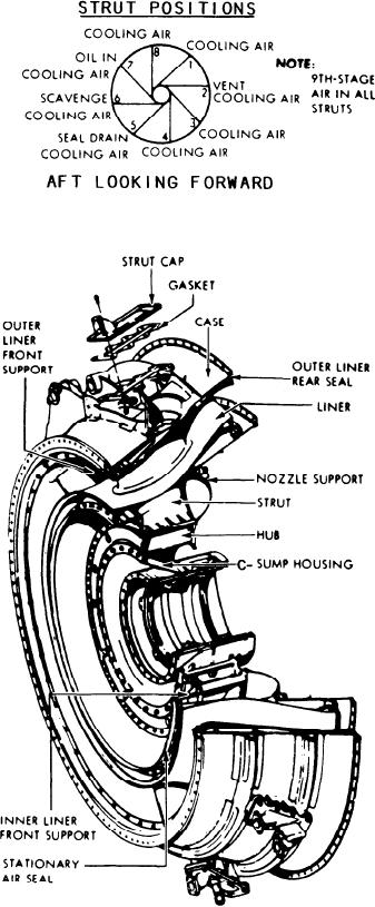
MID FRAME.--The turbine mid frame
(fig. 2-34) supports two areas. It supports the aft
end of the HP turbine rotor (No. 5 bearing); and
the forward end of the PT rotor (No. 6 bearing).
It is bolted between the aft flange of the
compressor rear frame and the forward flange of
the PT stator. The frame provides smooth
diffuser flow passage for HP turbine exhaust gas
into the PT. The frame hub is an open, drum-
shaped, one-piece casting with flanges to support
Figure 2-34.--Turbine mid frame.
the C-sump housing, stationary seals, inner liner
support, and PT first-stage nozzle support. The
The frame has ports for the HP turbine
C sump contains the No. 5 and No. 6 bearings.
exhaust thermocouples and pressure probes (not
Eight struts connect the hub to the outer case. The
shown). These ports also provide access for
struts provide passage for C-sump lubrication and
borescope inspection of the PT inlet area. The PT
scavenge oil, cooling air, sump vent, and seal
first-stage nozzle assembly is part of the frame.
drain services.
2-28