
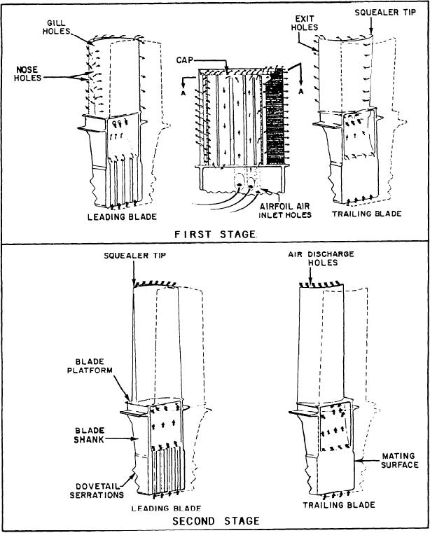
Figure 2-31.--HP turbine rotor blade cooling.
leading edge circuit provides internal convection
High-Pressure Turbine Blade Cooling.--Both
cooling by airflow through the labyrinth and out
stages of HP turbine blades are cooled by
through the leading edge nose and gill holes.
compressor discharge air (fig. 2-31). This air
Convection cooling of the trailing edge is provided
flows through the dovetail and through blade
by air flowing through the trailing edge exit
shanks into the blades. First-stage blades are
holes. Second-stage blades are cooled by
cooled by internal convection and external film
convection, with all the cooling air discharged
cooling. The convection cooling of the center area
at the blade tips.
is done through a labyrinth within the blade. The
2-26