
The turbine nozzles are contained in and
supported by the compressor rear frame. The
turbine mid frame, besides supporting the aft end
of the turbine rotor, also supports the front end
of the PT and contains the transition duct. The
gas flows throughout this duct from the HP
turbine section into the PT.
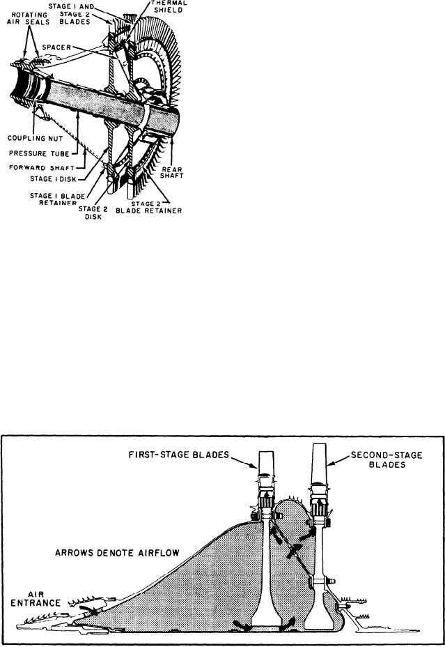
ROTOR.--The HP turbine rotor (fig. 2-29)
has a conical forward shaft, two disks with blades
and retainers, a conical rotor spacer, a thermal
shield, and a rear shaft. The front end of the
turbine rotor is supported at the compressor rotor
rear shaft by the No. 4 bearings. The rear of the
rotor is supported by the No. 5 bearing in the
turbine mid frame (C sump).
Energy extracted from the hot combustion
gases is transmitted to the compressor rotor
through the turbine rotor forward shaft. Two air
seals are on the forward end of the forward shaft.
The front seal helps prevent CDP air from enter-
Figure 2-29.--HP turbine rotor.
ing the sump. The other seal maintains CDP in
the plenum formed by the rotor and combustor.
This plenum is a balance chamber that provides
High-Pressure Turbine Section
a corrective force that minimizes the thrust load
on the No. 4B bearing.
The HP turbine section (fig. 2-28) has an HP
turbine rotor, the first- and second-stage turbine
High-Pressure Turbine Rotor Cooling.--The
nozzle assemblies, and the turbine mid frame. The
HP turbine rotor is cooled by a continuous flow of
turbine rotor extracts energy from the gas stream
compressor discharge air. This air passes through
holes in the first-stage nozzle support and in the
to drive the compressor rotor. The turbine rotor
forward turbine shaft. The air cools the inside of
is mechanically coupled with the compressor
rotor. The turbine nozzles direct the hot gas from
the rotor and both disks before passing between the
the combustor onto the rotor blades at the best
dovetails and out to the blades. Figure 2-30 shows
angle and velocity.
the airflow path for HP turbine rotor cooling.
Figure 2-30.--HP turbine rotor cooling.
2-25