
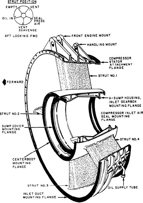
Figure 2-23.--Compressor front frame.
inlet guide vanes (IGVs) and first six stages of
components are the compressor front frame, a
stator vanes are variable; their angular position
compressor stator, a compressor rotor, and the
is varied as a function of GG speed and
compressor rear frame. The primary purpose of
compressor inlet temperature (CIT) by hydraulic
the compressor section is to compress air for
fuel pressure from the main fuel control
combustion. A secondary purpose of the
(MFC). This provides stall-free operation of the
compressor section is to provide air for engine
compressor throughout a wide range of speed and
cooling, sump seal pressurization, and bleed air
inlet temperature. Because these blades are able
for ship's service use.
to be set at different angles, the term variable
Air is drawn in through the front frame. Then
geometry applies to this compressor.
it passes through successive stages of compressor
rotor blades and compressor stator vanes. The air
FRONT FRAME.--The compressor front
is compressed as it passes from stage to stage.
frame (fig. 2-23) provides the forward attachment
After passing through 16 stages, the air has been
point for the GTE, supports the forward end of
compressed in the ratio of about 16 to 1. The
2-20