
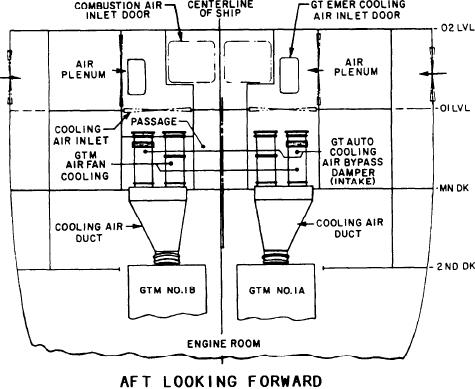
Figure 2-20.--FFG cooling system.
GAS TURBINE ENGINE ASSEMBLY
ship's service air system (SSAS). The vent
dampers are operable either automatically or
The LM2500 GTE is an axial-flow, split-shaft
manually from the PACC or the PLCC.
GTE with an annular-type combustion chamber.
FFG COOLING SYSTEM
The gas turbine assembly aboard ship has a GG,
In this system, the cooling air ducts to each
a PT, a high-speed flexible coupling shaft,
and inlet and exhaust components. The GG is
engine are made up of two parallel sections (fig.
composed of a FOD screen, a bellmouth, a
2-20). One section contains a cooling air fan and
16-stage variable geometry compressor, an
the other a cooling air bypass damper. The two
annular combustor, a two-stage high-pressure
sections join together before connecting to the
GTM. At low engine power the cooling air fan
(HP) turbine, an accessory drive system, controls,
and accessories. The accessory gearbox (AGB) is
in one leg supplies cooling air to the GTM. This
mounted on the GG. The PT is aerodynamically
acts to close the bypass damper in the other leg.
linked to the GG and is composed of a six-stage
As the engine power level passes 3,000 shaft
low-pressure (LP) turbine rotor, a low-pressure
horsepower (shp), the engine exhaust eductor
turbine stator, and a turbine rear frame. The high-
creates enough draft for the bypass damper to
speed flexible coupling shaft is connected to the
open. Both parallel legs then permit cooling air
power-turbine rotor and provides shaft power
to enter the GTM. The cooling air fan is shut off
to the ship's drive system. The GTE inlet
automatically at an engine power level of 3,000
components consist of the inlet duct and the
shp by the PCS.
centerbody (see fig. 2-2). The GTE exhaust
The PCS provides the control and status
components consist of the exhaust duct, the outer
indications for the cooling air fans at the PCC
cone, and the inner deflector (see fig. 2-11).
and the LOP. Both locations have controls for
manually starting the fans. They also have
GAS GENERATOR ASSEMBLY
automatic control of the fans after the GTE has
In this section we will individually describe the
been started. The fan local motor controller
GG assembly components and their functions.
provides the only controls for stopping the fan
These components are the FOD screen, bellmouth
in the manual mode. The cooling air bypass
and bulletnose, compressor, combustor, HP
dampers have position switches that show the
turbine, and accessory drive.
status of the bypass damper at the PCC.
2-18