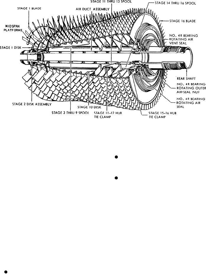
Figure 2-24.--Compressor rotor.
the compressor section, and forms a flow path
9-spool stage are joined by a single bolted joint
for compressor inlet air. Five struts (see strut
at stage 2.
positions, fig. 2-23) between the hub and the outer
case provide passages for lube oil, scavenge oil,
The 3- through 9-spool stage, the stage
seal pressurization air, and a vent for the A-sump
10 disk, and the 11- through 13-spool stage are
components. The bearings of the engine are
bolted at the stage 10 joint.
numbered 3 through 7. The No. 3 bearing, which
The 11- through 13-spool (with its integral
supports the forward end of the compressor rotor
and the inlet gearbox, are located in the A sump.
rear shaft) and the cantilevered 14- through
16-spool connect in a single bolted joint at stage
and CIT sensor (not shown) are mounted in the
13.
outer case. The No. 3 strut (6 o'clock position)
houses the radial drive shaft which transfers
An air duct, supported by the front and rear
shafts, routes stage 8 air aft through the center
power from the inlet gearbox to the transfer
gearbox (TGB) mounted on the bottom of the
of the rotor for pressurization of the B-sump seals.
frame.
Close vane-to-rotor spool and blade-to-stator
casing clearances are obtained with metal spray-
ROTOR. --The compressor rotor (fig. 2-24)
rub coating. Thin squealer tips on the blades and
vanes contact the sprayed material and abrasive
is a spool/disk structure with circumferential
action on the tips prevents excessive rub while
dovetails. The use of spools makes it possible
for several stages of blades to be carried on a
obtaining minimum clearance. The first-stage
blades have midspan platforms to reduce blade
single piece of rotor structure. The seven major
tip vibration.
structural elements and three main bolted joints
are as follows:
STATOR.--The compressor stator has four
The first-stage disk, the second-stage disk
sections bolted together. The top and bottom
cases are manufactured in matched sets. For
(with integral front stub shaft), and the 3- through
2-21

