
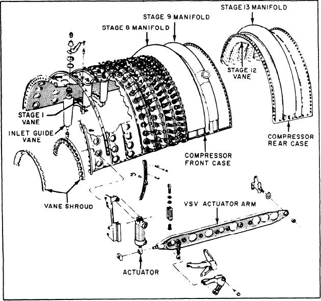
Figure 2-25.--Compressor stator.
clarity, figure 2-25 shows only the top two
Three bleed manifolds are welded to the stator
casings. Eighth-stage air, used for sump seal
sections and the major components of the
pressurization and cooling, is extracted from
compressor stator. The front casing contains
inside the annulus area at the tips of the hollow
the IGVs and stages 1 through 11. The IGVs and
eighth-stage vanes. Ninth-stage air, used for
the first six stages are variable to provide
stall-free operation. The variable vanes are
PT cooling, PT forward seal pressurization, and
PT balance piston cavity pressurization, is
actuated by a pair of master levers (one on each
extracted from between the ninth-stage vanes
side). The aft end of the master levers are
through holes in the vane bases. Thirteenth-stage
attached to pivot posts at about the 10th stage
air, used for cooling the second-stage HP turbine
on each side of the casing. Each of the lever's
nozzle, is extracted from between the thirteenth-
forward ends is positioned by a hydraulic actuator
stage vanes through holes in the vane bases.
which uses fuel oil as the actuating medium. The
operation of the IGVs and variable stator vanes
REAR FRAME.--The compressor rear frame
(VSVs) are covered later in this chapter. The
(fig. 2-26) has an outer case, a hub containing
remaining vanes are stationary. The rear casing
the B sump, and 10 struts attaching the hub to
contains the 12th through the 16th stages, which
the outer case. The outer case supports the
are also stationary.
2-22