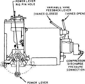
position; it adjusts the fuel flow to maintain the
desired speed set by the power lever. The MFC
is a hydromechanical device which operates by use
of fuel-operated servo valves. The MFC has two
primary functions. One is to control GG speed
(schedules acceleration fuel flow and deceleration
fuel flow). The other controls stator vane angle
(for stall-free, optimum performance over the
operating range of the GTE).
The MFC controls GG speed as a function of
power lever position. The power level is set
electrically by a signal from the FSEE. Movement
of the power lever changes speed demand. A
flyweight governor senses GG speed. This adjusts
the fuel flow as necessary to maintain the speed
set by the power lever. Three fuel schedules
are established by the control: acceleration,
deceleration, and minimum fuel schedules. The
acceleration schedule limits fuel flow necessary
for acceleration to prevent overtemperature and
stall. The deceleration schedule limits the rate of
fuel flow decrease to prevent combustion
Figure 2-42.--Main fuel control.
flameout during deceleration. The minimum fuel
schedule limits fuel flow for starting to prevent
per square inch absolute (psia); it reseats at or
overtemperature. The MFC senses CIT, CDP,
above 1,325 psia. These features protect the pump
and NGG, which biases the fuel schedules as a
function of atmospheric and engine operating
and downstream components against excessive
conditions.
system pressures.
The MFC schedules the VSVs as a function
The fuel filter (5) is an HP filter mounted on
of GG speed and CIT. Actual position of the
the fuel pump and flange-ported to eliminate
VSVs is sensed by the control via a position
external piping. The head houses a bypass relief
feedback cable. One end of the feedback cable
valve (6); the bowl houses the filter element. The
is connected to the left master lever arm. The
filter element is rated at 46 microns nominal
other end is connected to the feedback lever on
and 74 microns absolute. It prevents larger
the MFC.
contaminants from being carried into the MFC.
High-pressure fuel flows from the fuel pump
through the flange port and enters the filter bowl.
Pressurizing Valve
The fuel then flows from the outside of the filter
element to the center, up into the head, out the
The pressurizing valve pressurizes the fuel
flange return port, and back into the fuel pump.
system. It ensures adequate fuel control servo
There, it is routed to the MFC. If the filter
supply pressure and VSV actuation pressure.
becomes clogged, the bypass relief valve opens at
These pressures are essential for proper fuel and
35 pounds per square inch differential (psid).
stator vane scheduling during GG operation at low
From the MFC the fuel goes to the fuel shutdown
fuel flow levels. The valve is a fuel pressure-
valves, the purge valve, the fuel manifold, and
operated, piston-type valve. The piston is held on
finally the fuel nozzles.
its seat (closed) by spring force and fuel pressure
(reference pressure) from the MFC. Servo
pressure is 110 to 275 psig. The MFC discharge
Main Fuel Control
fuel (metered fuel for combustion) enters the
pressurizing valve at the opposite side of the
The MFC (fig. 2-42) is basically a speed
piston. When MFC discharge pressure is 80 to 130
governor which senses NGG and power lever
2-36

