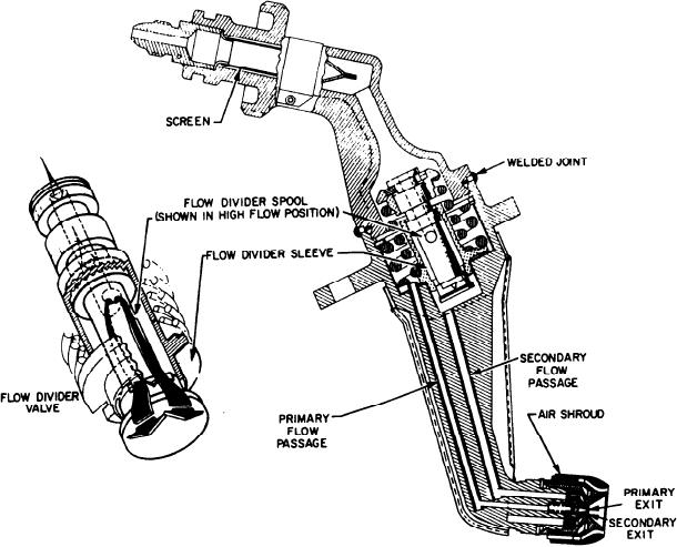
Figure 2-44.--Fuel nozzle.
Compressor Inlet Temperature Sensor
(fig. 2-44) is a dual-orifice, swirl atomizer
with an internal flow divider. The fuel nozzles
The CIT sensor has a constant-volume, gas-
produce the desired spray pattern over the full
filled probe and a metering valve. This sensor
range of fuel flow. Fuel enters the nozzle
controls or meters fuel across an orifice. It is
through a single tube, flows through a 117-micron
mounted at the 8 o'clock position in the
screen, and then the flow divider. When the
compressor front frame. The sensing probe
nozzle is pressurized, primary fuel flows through
projects through the frame into the airstream.
a drilled passage and tube assembly in the
Since the temperature sensing probe has a
nozzle shank. It then flows through the primary
constant volume, the gas pressure inside the
spin chamber and into the combustor. When
probe is equal to the temperature. This pressure
fuel pressure to the nozzle rises to 330 to 350 psig,
is connected to a sensing bellows, which, in
the flow divider opens and introduces secondary
turn, is connected to the metering valve. Fuel
fuel flow. The secondary fuel flows through
from the MFC enters the CIT sensor. There it is
the flow divider, through a passage in the
metered by the metering valve proportional to the
nozzle shank, into the secondary spin chamber,
temperature at the sensing probe. It is then used
and mixes with the primary flow as it enters
as a scheduling parameter by the MFC.
the combustor. An air shroud (swirl cup)
around the nozzle tip scoops a small quantity of
Variable Stator Vanes
air from the main airstream to cool the nozzle
The VSVs are positioned by two hydraulic
tip. This retards the buildup of carbon deposits
actuators operated by fuel pressure from the
on its face.
2-38

