
MFC. The MFC has a variable vane scheduling,
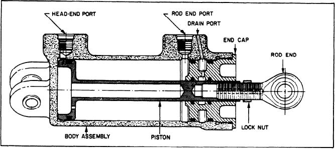
forward flange at the 3 o'clock and 9 o'clock
3-dimensional (3-D) cam which is positioned by
positions. They are connected to the VSVs
NGG and CIT signals; it has a variable vane
through master lever arms and actuation rings.
feedback mechanism which receives a vane
The MFC schedules HP fuel to either the
position signal from a linkage connected to
head-end port (opens VSVs) or the rod-end
the VSV master lever; it also has a variable
port (closes VSVs). Control parameters sensed
vane pilot valve positioned as a result of the
by the MFC to schedule variable vane angle
comparison of the scheduling cam position
are NGG, CIT, and stator vane angle via a
feedback cable. The feedback cable is connected
and the feedback signal. Changes in engine
speed rotate the scheduling cam; changes in
on one end to the left master lever arm
CIT reposition the cam. Movement of the cam
and on the other end to the MFC.
repositions the pilot valve. The pilot valve
ports HP fuel (pump discharge pressure) to
Power Lever Angle Rotary Actuator
either the rod end (closing) or head end
(opening) of the vane actuators; it vents
the other end to bypass pressure. The variable
The PLA rotary actuator is an electro-
vane actuating linkage mechanically transmits
mechanical device that interfaces the PLA
actuator electronics in the FSEE with the MFC
the actuator movement to the variable vanes
of the GTE. It moves the internal components
and IGVs. A flexible cable is attached to the
linkage. It transmits a feedback signal to the
of the MFC to control fuel flow to the engine.
MFC. The feedback mechanism in the MFC
It has a dc servomotor, a reducing gear, a
repositions the pilot valve to terminate the
slide potentiometer, a tachometer generator,
actuator signal when the vanes reach the scheduled
mechanical linkage, and an electrical line filter.
position.
The PLA actuator is mounted on the fuel pump;
it is connected to the fuel control power lever
through a mechanical linkage. It is electrically
Variable Stator Vane Actuators
connected to the FSEE.
The VSV actuators (fig. 2-45) are single-ended,
Signals from the PLA actuator electronics,
located in the FSEE, are converted by a servo-
uncushioned hydraulic cylinders which are driven
in either direction by HP fuel. The piston stroke
mechanism into mechanical action that positions
is controlled by internal stops. The two actuators
the fuel-control power lever. Feedback of PLA
are mounted tangentially on the compressor stator
and rate of change are sent to the FSEE. A
Figure 2-45.--VSV actuator, cross-sectional view.
2-39