
from entering the combustion chamber and
gaps break down, a current (caused by a partial
causing excessive start temperatures. The igniters
discharge of the tank capacitors) through the HF
are secured by an electronic signal at 4,500 rpm.
transformer and in conjunction with the HF
By this time combustion has occurred and the
capacitor causes a series resonant condition to
engine has reached self-sustaining speed.
exist. It also causes HF oscillations to occur in
the output circuit. These HF oscillations cause
Ignition Exciters
ionization of a recessed spark gap of the igniter
The ignition exciters are the capacitor
plug. A low-resistance path now exists for total
discharge type. They are located on the right side
discharge of the tank capacitor, producing a high-
of the front frame. They are attached to special
energy spark used to ignite the fuel within the
mounts that absorb shock and vibration. The
combustor. The spark rate is determined by the
exciters operate on 115-volt ac, 60-Hz input. The
total rectifier circuit resistance. This controls the
power is transformed, rectified, and discharged
resistive capacitive (RC) time constant in the
in the form of capacitor discharge energy pulses.
charging circuit.
It then flows through the coaxial shielded leads
to the spark igniters.
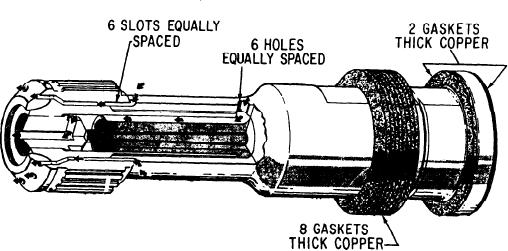
Spark Igniters
When the starting switch is closed, shipboard
The spark igniters (fig. 2-51) are the surface
60-Hz power is applied to the exciter circuits. The
gap type. They have internal passages for air
exciter has input, rectifier, discharge, and output
cooling and air vents. These passages prevent the
circuits. The input circuit includes a filter that
accumulation of carbon in interior passages. The
prevents feedback of radio-frequency interference
igniter has a seating flange with attached copper
(RFI) (generated within the exciter). The filter also
gaskets for sealing purposes. Grooves in the outer
prevents introduction of electromagnetic inter-
surface of the tip and axial holes cool the outer
ference (EMI) (generated externally). The input
and inner electrodes with compressor bleed air.
circuit also includes a power transformer that
The surface gap will ionize at 8,500 volts when
provides step-up voltage for the rectifier circuit.
dry and 15,000 volts when wet. A discharge of
The full-wave rectifier circuit includes diodes that
2 joules of energy exists across the gap.
rectify the high-voltage ac. This circuit also
includes capacitors that are arranged in a voltage
doubler configuration. Tank capacitors store the
CAUTION
dc voltage developed in the rectifier circuit. They
store this voltage until the potential developed
This energy level is lethal. You should
reaches the breakdown point of spark gaps in the
never contact the output from the spark
discharge circuit. The discharge circuit contains
exciter, the leads, or the igniter. You must
the spark gaps, high-frequency (HF) capacitor,
use a grounding probe to ground the ignition
resistors, and HF transformer. When the spark
system when maintenance is performed.
Figure 2-51.--Spark igniter.
2-45