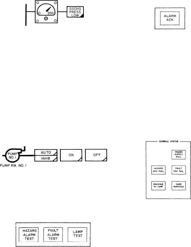
psig and monitors the fire pump discharge
push button acknowledges flashing alarms on the
firemain control panel. If the alarm condition still
pressure. The alarm indicator illuminates amber
exists, the alarm indicator will illuminate steadily.
to indicate a low pump discharge pressure.
The alarm indicator extinguishes when the alarm
condition no longer exists.
Located to the right of each fire pump are
The final section on the firemain control
three push buttons that control the starting and
panel, right side, is labeled CONSOLE STATUS.
stopping of the fire pump. The first push-button
indicator is a split-legend push button labeled
This section contains five status indicators. The
first indicator is labeled POWER SUPPLY FAIL.
AUTO and INHB. In the AUTO position, the
It illuminates red to indicate one of the dc power
designated fire pump is set for automatic starting
upon loss of firemain pressure. In the INHB
supply voltages has dropped below its limit. The
second indicator, labeled HAZARD OSC FAIL,
position, the designated fire pump is inhibited
illuminates amber to indicate a failure of the
from automatically starting. The fire pump can
hazard oscillator. The third indicator, labeled
be started manually. The second push-button
FAULT OSC FAIL, illuminates amber to indicate
control indicator is labeled ON. Each ON push
a failure of the fault oscillator. The fourth
button provides for manual starting of the
indicator is labeled CONSOLE HI TEMP. It
associated fire pump from the DCC. It illuminates
illuminates red to indicate one of the three
green to indicate the fire pump is running. The
third push-button control indicator is labeled
temperature switches has exceeded 168F. The
OFF. The OFF push button provides for manual
fifth indicator, labeled CARD REMOVED,
illuminates amber to indicate a circuit card in the
stopping of the associated fire pump from the
DCC is removed or improperly seated.
DCC and illuminates white to indicate the fire
pump is secured.
The firemain control panel has a HAZARD
ALARM TEST, a FAULT ALARM TEST, and
a LAMP TEST push-button indicator on the left
side. These indicators function in a manner similar
to that of the hazard detection panel hazard, fault,
and lamp tests. These push buttons test the
Rear Panel (Back of Console)
circuits of the firemain control panel.
The rear of the DCC consists of five sections.
These sections are labeled card cages, relay
panel assembly, fuse and circuit breaker panel,
calibration panel, and power supply drawers. The
following paragraphs describe the components of
this panel. Refer to figure 9-20 during this
discussion.
Located below the firemain control panel test
CARD CAGES.--Sections 1A3A1, 1A2A1,
push buttons is a push-button control indicator
and 1A1A1 house the three card cage assemblies
labeled ALARM ACK. When depressed, this
9-26

