
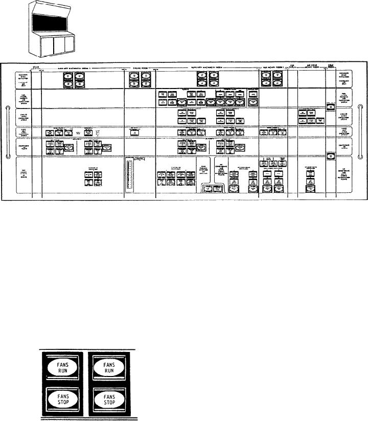
Figure 9-23.--ACC vertical panel.
in the LOCAL/REMOTE mode. This allows for
The first push-button indicator switch is
additional controller operations from both the
labeled FANS RUN. It is used to start one supply
local controller and the remote panel. If an
and one exhaust fan in the machinery space. The
emergency exists, the switches at the ACC are
second push-button indicator switch, also labeled
used. The local controller switch must be in the
FANS RUN, is used to start the other supply and
LOCAL/REMOTE position for the push buttons
exhaust fan in that machinery space. The third
on the ACC to be operational.
push-button indicator switch, labeled FANS
STOP, is used to stop the first set of supply and
Fuel Filling, Transfer, and
exhaust fans. The fourth ventilation push-button
Purification System Section
indicator switch, also labeled FANS STOP, is
used to stop the second set of supply and exhaust
This section has controls and indicators for
fans.
the purifier, transfer pump, and stripping pump
in the fuel filling, transfer, and purification
system. The controls have EMERGENCY STOP
push buttons for each of the components.
Indicators are provided to monitor the status of
purifier speed, discharge, and vibration and the
status of the transfer pump and the stripping
pump. All the equipment monitored is located in
AMR No. 2.
The ACC vertical panel contains five push-
button controls and indicators for each fuel
purifier. Since both purifier controls and
The machinery space ventilation fans are
indicators are identical, only one set will be
located in the engine room and AMRs No. 1,
discussed. The first indicator is labeled NORMAL
No. 2, and No. 3. There are supply and exhaust
SPEED RUNNING. This indicator illuminates
fans in each room. Under normal conditions, the
green to indicate the fuel transfer purifier is
fans are started from the local controllers and left
9-31