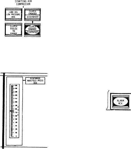
The starting air compressor (SAC) section of
The main engine starting air system provides
the ACC contains the four control indicator push
compressed air to the gas turbine (GT) pneumatic
buttons for the three SACs. Since each SAC is
starter. The starter rotates the GG for starting,
identical, only one set of push buttons will be
motoring, or water washing. The starting air
discussed.
system uses compressed air supplied from one of
The first indicator in this section is labeled
three SACs. In an emergency, it can use
LUBE OIL LOW PRESSURE. It illuminates red
compressed air from the bleed air system of an
to indicate the LO pressure at the SAC is
operating engine. Only one compressor is used for
below the preset limit. The second split-legend
starting, motoring, or water washing. Two of the
indicator is labeled CLUTCH ENGAGED and
compressors are located in AMR No. 2; the third
DISENGAGED. The top portion of this indicator
is located in AMR No. 3.
illuminates to indicate the SAC clutch is engaged.
The bottom portion of the indicator illuminates
NOTE
to indicate the clutch is disengaged. The third
indicator, labeled CLUTCH FAILED TO
The location of each SAC may be different
ENGAGE, illuminates red to indicate failure of
on each flight of the FFG-class ship.
the SAC clutch to engage. The last split-legend
indicator control push button in this section is
Each SAC is driven by an associated diesel
labeled CLUTCH ENGAGED and DISENGAGED.
generator set. The compressor is driven by the
This push button allows the ACC operator to
diesel engine via a step-up gearbox and hydraulic
engage or disengage the SAC clutch.
clutch. The clutch can be engaged whenever the
electrical load on the respective SSDG is below
666 kW. During compressor operation, should the
kW load on the SSDG exceed 666 kW, the clutch
will disengage.
Alarm Acknowledge
The ALARM ACK push button is located in
the lower, center portion of the ACC vertical
panel. When an out-of-tolerance condition occurs
in a system being monitored at the ACC, the
The next item on the ACC vertical panel is a
associated fault alarm actuates. The audible alarm
vertical reading pressure gauge labeled DIS-
is accompanied by a flashing visual light. The
CHARGE MANIFOLD PRESS. This gauge
operator acknowledges the alarm by depressing
provides a continuous reading of the discharge
the ALARM ACK push button. The audible
manifold air pressure.
portion of the alarm is silenced and the visual light
stops flashing but remains illuminated. The light
remains illuminated until the cause of the alarm
has been cleared. This push button is used to
acknowledge any alarm on the ACC.
Processor Generated Alarm
The processor is a special-purpose computer
located in the EPCC. When an out-of-tolerance
condition occurs on equipment being monitored
at the ACC, the equipment sensor transmits a
signal to the equipment fault alarm circuitry in
9-35

