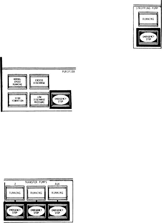
allows the operator to stop the stripping pump
running at normal speed. The second indicator,
in the event of an emergency.
labeled EXCESS DISCHARGE, illuminates red
to indicate the flow through the breakover
switch is excessive. This usually indicates a loss
of purifier seal. The third indicator, labeled HIGH
VIBRATION, illuminates red to indicate excessive
vibration of the fuel purifier. The fourth indicator
is labeled LOW DISCHARGE PRESSURE. It
illuminates red to indicate the purifier discharge
pressure has dropped to 20 psig. The push-button
switch, labeled EMERGENCY STOP, is provided
to allow the ACC operator to stop the fuel purifier
in the event of an emergency.
The fuel filling, transfer, and purification
system is used to distribute fuel from the deck
filling connections to the fuel storage and
overflow tanks. It also discharges fuel from
the storage and overflow tanks via the deck
connections. It is used to transfer fuel between
storage tank groups to adjust trim and list. One
of its primary jobs is to transfer fuel to the
service tanks via the fuel transfer heaters and
centrifugal purifiers. The system is designed for
local start-up and unattended operation.
Chilled Water Circulating System Section
The TRANSFER PUMPS section of the ACC
vertical panel contains controls and indicators
This section contains the alarms and indicator
for two fuel transfer pumps and one auxiliary
lights that monitor the chilled water circulating
transfer pump. The first three indicators, labeled
system and indicate the status of the chilled water
RUNNING, illuminate green to indicate the
circulating pump. The alarms alert the operator
No. 1, No. 2, or auxiliary fuel transfer pump is
to three occurrences: (1) a high or low chilled
running. The next three push-button switches,
water temperature condition, (2) a circulating
labeled EMERGENCY STOP, allow the operator
pump discharge pressure failure, or (3) a low level
to stop the respective transfer pump in the event
in the chilled water expansion tank.
of an emergency.
The ACC vertical panel contains five push-
button controls and indicators for the each chilled
water system. Since controls and indicators for
the three chilled water systems are identical,
only one set will be discussed.
The first indicator is labeled HIGH TEMPER-
ATURE. It illuminates red to indicate the chiller
outlet temperature has exceeded 45F. The
second indicator, labeled PRESSURE FAILURE,
illuminates red to indicate the chilled water
circulating pump discharge pressure has dropped
below 30 psig. The third indicator, labeled LOW
TEMPERATURE, illuminates red to indicate the
chiller outlet temperature has dropped below
35F. The fourth indicator, labeled EXPANSION
The STRIPPING PUMP section contains the
TANK LOW LEVEL, illuminates red to indicate
control and indicator for the fuel stripping pump.
the expansion tank water level has dropped below
The RUNNING indicator illuminates green to
20 percent of the tank capacity. The last indicator
indicate the stripping pump is running. The push-
in this section is labeled CIRCULATE PUMP
button switch, labeled EMERGENCY STOP,
9-32

