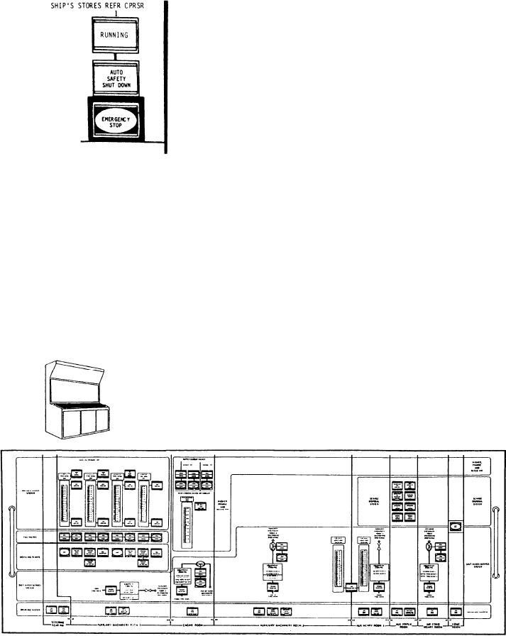
STOP, allows the operator to stop the refrigera-
potable water system; the masker, prairie,
tion compressor in the event of an emergency.
fin stabilizer, and bleed air systems; the
sewage disposal system; the distilling plants;
the saltwater service system; and the drainage
system. This panel is shown on figure 9-24.
Refer to figure 9-24 as you read the following
descriptions.
Potable Water System
Section
The indicators for the potable water system
include tank level meters and indicators for
the status of the four potable water tanks,
the two potable water pumps, and the hot
potable water pump. High- and low-level
The ship's stores refrigeration plants allow for
alarms are provided for each of the four
the preserving of perishable food stores. The
tanks. The operator can use the demand
plants serve one freeze room and two chill rooms.
displays to monitor the tank levels and the
Each plant has a rated capacity of 1.1 tons of
potable water system pressure. Push-button
refrigeration. Both plants are located in AMR
OPEN/CLOSE switches for the potable water
No. 1. They are designed for local start-up and
tank fill valves allow the operator to coordinate
unattended operation.
the tank filling operation.
ACC LOWER PANEL
The first indicator in the potable water
system section is labeled PUMP 2 RUNNING.
The ACC lower panel contains the switches
It illuminates green to indicate that potable
and indicators that control and monitor the
water pump No. 2 is running. The indicator
Figure 9-24.--ACC lower panel.
9-37

