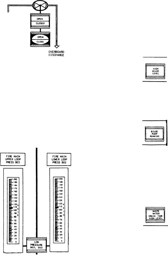
portion of the indicator illuminates red to indicate
Drainage System Section
the overboard discharge valve is closed. The
second split-legend control push button is labeled
The drainage system indicators include alarms
OPEN and CLOSE. This push button allows
that indicate a high liquid level in the bilge of each
control of the motor-operated overboard dis-
of the eight rooms being monitored, a high level
charge valve. There are three pairs of split-legend
in the waste water drain tanks in the three AMRs,
indicators and control push buttons in this
and a high level in the oily waste water holding
section of the ACC.
tank. Indicators also show the status of the
steering gear room drain pump and the bilge
pump in AMR No. 2. The demand display may
be used to monitor the level in the oily waste water
holding tank.
The first alarm indicator is labeled HIGH
BILGE LEVEL. It illuminates red to indicate the
liquid level in the bilge has exceeded the preset
limit. There are eight HIGH BILGE LEVEL
alarm indicators in this section of the ACC.
The first vertical reading meter in this section
is labeled FIRE MAIN UPPER LOOP PRESS.
This meter, scaled in psig, provides continuous
monitoring of the upper firemain loop pressure.
A second vertical reading meter, labeled FIRE
The second indicator is labeled BILGE PUMP
MAIN LOWER LOOP PRESS, provides con-
RUNNING. It illuminates green to indicate that
tinuous monitoring of the lower firemain loop
the steering gear room bilge pump is running.
pressure. Located between the two vertical reading
meters is an alarm indicator labeled LOW
PRESSURE. This indicator illuminates red to
indicate that the firemain pressure in either loop
has dropped to 110 psig.
The alarm indicator is labeled WASTE
WATER DRAIN TANK HIGH LEVEL. It illumi-
nates red to indicate that the level in the waste
water drain tank has exceeded the preset limit.
There are three WASTE WATER DRAIN TANK
HIGH LEVEL alarm indicators in this section of
the ACC.
The fourth indicator is labeled OILY WASTE
DRAIN BILGE PUMP RUNNING. It illuminates
9-41

