
green to indicate that the oily waste drain tank
bilge pump is running.
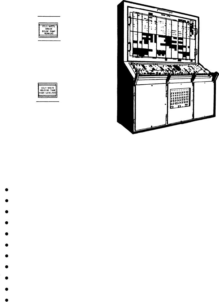
The last alarm indicator in this section is
labeled OILY WASTE HOLDING TANK HIGH
LEVEL. It illuminates red to indicate the level of
the oily waste holding tank has exceeded the preset
limit.
DAMAGE CONTROL CONSOLE
FOR THE FFG-7 CLASS SHIPS
The DCC on the FFG-7 class ships has many
of the same features as the DCC on the DD-963
Figure 9-25.--Damage control console (FFG-7).
and CG-47 class ships. (See fig. 9-25.) From this
console, an operator can monitor and control
DCC UPPER PANEL
many of the damage control systems installed on
the FFG-7 class frigates. The DCC is located on
the damage control side of CCS. These systems
The upper panel of the DCC, shown in figure
9-26, is used to monitor most of the systems of
include the following components:
the DCC. This panel is divided into three major
sections, with each section further divided into
AFFF sprinkling system valves
subsections. The upper panel also contains a
power monitoring section. The three major
sections are labeled as follows:
High water alarm
1. Misc. Fire Fighting
2. Alarm and Detection
Sprinkling systems
3. Ventilation
High temperature alarms
The DCC upper panel displays the four fire
zones on the FFG-class ship. During the
Supply fans
discussion of the alarms, indicators, and controls
of this panel, only FIRE ZONE 1 will be
Fire zone doors
discussed. The other five fire zones are identical,
with the exception of the indicator labels.
Exhaust fans
Power Monitoring Section
Recirculating fans
This section contains eight indicators to
Ducting closures
display the status of various console power
requirements. The first two indicators are located
Firemain pumps and valves
9-42